Continue to Site

Welcome to our site!

Electro Tech is an online community (with over 170,000 members) who enjoy talking about and building electronic circuits, projects and gadgets. To participate you need to register. Registration is free. Click here to register now.

  • Welcome to our site! Electro Tech is an online community (with over 170,000 members) who enjoy talking about and building electronic circuits, projects and gadgets. To participate you need to register. Registration is free. Click here to register now.

How to test a flow meter sensor

Status
Not open for further replies.

Kal_B

Member
Hello guys,

I have one of those flow meters a 2536 Model
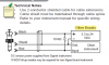
and I was told that it doesn't work but I am not certain. The sensor is plugged into a circuit board that is connected to a PC which in turn controls a couple of pumps. I'm thinking it could be anything from the sensor to the board or even the PC program so I would like to test the sensor independently to verify its operating condition. I was told that it contain a simple Reed switch but if that's the case why does it require 5Volts, and why does it say open collector. I'm thinking more like hall sensor. I believe it is connected to the circuit board as described in the attachment as "other brands"

What would be the way to test it ?

Thanks
Kal
 

Attachments

  • Signet 515-2536 Rotor-X Flow Sensors (English).pdf
    404 KB · Views: 203
What is the connection show in the attached picture that is connected to the ground and has like a skinny oval shape going around the wire, is that the pull up resistor they mentioned?

Thanks
Kal
 

Attachments

  • sginet.png
    sginet.png
    29.1 KB · Views: 130
Hello Kal_B.

If it is in fact just a reed switch then an ohm meter should be able to detect open and closed circuit as you rotate the paddle. I work on rainfall sensors that use a reed switch and a tipping bucket with a magnet. The sensor is connected to a datalogger that just counts pulses and the k factor determines how much rainfall per pulse.
Sounds similar to this flow sensor. Do you see any magnets?

The data sheet shows a square wave output which could be accomplished with a reed switch or possible hall sensor as well. Try an ohm meter first and if no change in continuity is detected then try powering it per the wiring diagram and check for square wave output.

rfranzk
 
Generally this sort of paddlewheel flow sensor uses small magnets embedded inside the plastic wheel. Most use this with a Hall Effect sensor embedded in the body so they output pulses. In your case it appears these units use open collector output with an external pullup resistor. Power the sensor with the suggested voltage and place a 10 K Ohm pullup resistor across the output and power in as shown. Spin the paddle manually and look for pulses on the output. That will tell you if the sensor assembly is working. Then note the K factor for your specific sensor and pipe diameter. Also keep in mind with sensors like this you need X number of pipe diameters upstream and x number downstream. Normally around 10X and 5X. Meaning with a 1/2 inch pipe you want at least 5 inches upstream and 2.5 inches down stream of straight pipe.

Ron
 
Status
Not open for further replies.

New Articles From Microcontroller Tips

Back
Top