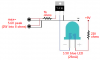
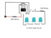
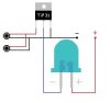
Hi, recently I've found circuits for a TIP31 connected to an audio jack to make an LED change it's brightness to the music. I'm wondering, is it possible to make the LED dim when the music gets louder, instead of getting brighter? And how would I do this?
Attachments
Last edited: