AlainB
Member
Hi,
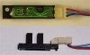
I got many of those from a photocopier. I would like eventually to use them as limit switchs for a CNC machine. The problem is that they are designed to work at 24 volts. It is not convenient for me. I'd rather prefer them at 5 volts.
How should I do that, if possible?
Thank!
Alain

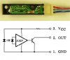
Datasheet:
https://www.alldatasheet.com/datasheet-pdf/pdf/126557/TOSHIBA/TLP1224C1.html?
I got many of those from a photocopier. I would like eventually to use them as limit switchs for a CNC machine. The problem is that they are designed to work at 24 volts. It is not convenient for me. I'd rather prefer them at 5 volts.
How should I do that, if possible?
Thank!
Alain
Datasheet:
https://www.alldatasheet.com/datasheet-pdf/pdf/126557/TOSHIBA/TLP1224C1.html?
Attachments
Last edited:


")

