Continue to Site

Welcome to our site!

Electro Tech is an online community (with over 170,000 members) who enjoy talking about and building electronic circuits, projects and gadgets. To participate you need to register. Registration is free. Click here to register now.

  • Welcome to our site! Electro Tech is an online community (with over 170,000 members) who enjoy talking about and building electronic circuits, projects and gadgets. To participate you need to register. Registration is free. Click here to register now.

how to read port

Status
Not open for further replies.

blibala

New Member
how to read individual pin status on each port of PIC16F877 using PIC basic pro.
can i read like this?
TRISA=1
IF PORTA.0=1 THEN
.
.
.
.
ENDIF
 
Yes...
The command TRISA = 1
will put 1 (binairy 00000001) into TRISA, making pins 1-7 outputs, and pin 1 an input

You should then be able to read it with your if command
 
but it didint produce proper with it.my testing code for PIC16f84A is as follow:

LOOP:
TRISA=3 '00000011
TRISB=0 '00000000
PORTA.2=1 'RA2 ALWAYS ON
High PORTA.4 'RA4 ALWAYS ON

IF PORTA.0=1 Then 'IF RA0 SWITCH IS CLOSED
High PORTA.3 'LED RA3
PORTB.2=1 'LED RB2
High PORTB.3 'LED RB3
PORTB.4=1 'LED RB4
Else
PORTB.5=1 'LED RB5
ENDIF
END


is this code wrong?
when i havent closed the PORTA.0 switch, all the LEDs inside the loop are already glowing. is it i read the status of PORTA.0 wrongly?

[/quote]
 
First off all, there's a label LOOP at the top of your code, but you don't jump to it... There should be a GOTO loop near the end of your code

secondly, how did you connect the switch?
You need to get the pic input in a known state at all times, never leave it floating.

The first picture is not good. If you press the button, the input is at 5V, but when you release the button the input is floating, this may cause the pic to see a '1' anyway.
 

Attachments

  • Pic_switch.JPG
    Pic_switch.JPG
    6.7 KB · Views: 669
if the pin is opne drain type if configured as ouput, i need to insert a pull up resistor. how do i implement it to connect a LED to it? plz show me the diagram.
 
i have tested the program once again and this time work nice.only the LED connected to open drain output RA4 is out of control.

one doubt. after the program completes one cycle and loops back, the LEDs are still glowing. how to initiate it so that it starts from zero LEDs glowing?
 
just put code to put all the leds out again at the top of your code below the loop

LOOP
LOW PORTA.3
LOW PORTB.2
...
 
if i make RA4(PIC16F84A) an output pin and i want to connect a LED to it, however since RA4 is a open drain type, how should i connect it with LED?
i mean how to connect the LED and pull up resistor?
i coonect in this way, and is it correct?

but it seems to be not working properly. if i remove the PIC,the LED still glow. the LED is glowing cos it is direcly connected to the power supply.

what is the purpose of the weak pull up at port b in the most PIC mcu?do i need to enable it?
 

Attachments

  • sample.JPG
    sample.JPG
    6.6 KB · Views: 638
As you know RA4 in that PIC is open drain. What this means is that you are only going to be able to pull low when it is an output. So if you were to have and LED (with it's resistor) conected to +5V and the other end to the RA4, when you make that PIN low the LED will light. In other word RA4 can only sink current.

Form the PBP manual:
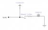
Another example of potential disaster is that PORTA, pin 4 exhibits unusual behavior when used as an output. This is because the pin has an open drain output rather then the usual bipolar stage of the rest of the output pins. This means it can pull to ground when set to 0, but it will simply float when set to a 1, instead of going high. To make this pin act in the expected manner, add a pull-up resistor between the pin and 5 volts. The value of the resistor may be between 1K and 33K, depending on the drive necessary for the connected input. This pin acts as any other pin when used as an input.

To give you an idea of why they are weak pull up resitors you have to see the datasheet. According to that, the PORTB weak pull-up current has a maximum of 400uA current available..... now that is weak :lol: The purpose of these pull-ups is to make the pin high in the absence of a signal, so that it doesn't stay floating around. And allows you to reduce the parts you need too :)

Ivancho
 
I could not find a suitable drawing, but if you look around you will find something on google. The closest I found without searching much is the following..... just connect it to the RA4 and set RA4 to low to light the LED**broken link removed**

Ivancho
 
Status
Not open for further replies.

Latest threads

New Articles From Microcontroller Tips

Back
Top