Continue to Site

Welcome to our site!

Electro Tech is an online community (with over 170,000 members) who enjoy talking about and building electronic circuits, projects and gadgets. To participate you need to register. Registration is free. Click here to register now.

  • Welcome to our site! Electro Tech is an online community (with over 170,000 members) who enjoy talking about and building electronic circuits, projects and gadgets. To participate you need to register. Registration is free. Click here to register now.

How to power up two stereo audio amplifiers from a single source of power supply

Status
Not open for further replies.

learning

Member
Could you tell me how to power up two stereo audio amplifiers from a single source of power supply?

Configuration:


4 x Woofers (4 ohm/20 watts)
4 x Tweeters (4 ohm/40 watts)
4 x 2-way Crossover Network (40 watts).


Total wattage is 480 watts

Please tell me how I can feed the power supply to these two stereo amplifiers (240 watts each) from a single power supply source like an AC adaptor (24V / 6A) only. I don't like to use any kind of transformer for it.

Just help me!
 
Last edited:
The amp sees an 8 Ohm load at eg. 500Hz and an 8 Ohm load at 5KHz, whether through a crossover or when feeding a wide range speaker or an 8 ohm dummy load.

If can give power at both frequencies regardless of a crossover or not.

If your hypothesis was correct, every multi-driver cabinet using crossovers would be showing the same effect; three-way cabs would be 1/3rd the stated impedance etc. and I'm pretty sure that would mean amp makers warning of possible overload or damage because of the supposed effect.
 
I did not say that one 8 ohm speaker is 4 ohms when it produces two frequencies.
Instead I said that an 8 ohm woofer plus an 8 ohm tweeter both playing tones in the middle of their frequency ranges are a load of 4 ohms on the amplifier.
You're not helping anything posting gibberish - two 8 ohm speakers connected via a suitable crossover gives an 8 ohm speaker.

As I said previously, they 'may' be a dip at crossover frequency, but it won't be 4 ohms, and the speakers themselves will most likely have lower dips across their range anyway.
 
An example is 10V RMS into the 8 ohm woofer at 400 Hz plus another 10V RMS into the 8 ohm tweeter at 5kHz.
Each speaker is drawing 12.5W for a total of 25W.

Of course the load is 4 ohms because the two speakers are in parallel. Luckily, music and speech infrequently use high power in the tweeter.

Acid rock "music" has the amplifier clipping all the time producing almost double the power of no clipping and those amplifiers survive the overloading.

Talking about harmonics, assume the amplifier has an input sinewave plus many harmonics which creates squarewaves. The original sinewave is 10V RMS into a single 8 ohm speaker which is 12.5W from the amplifier.
But producing the squarewaves the output from the amplifier is 14.14V peak (the same peak voltage as the sinewave) which is 25W alternating.
 
Maybe the amplifier will not be overloaded when producing a low frequency into a woofer plus a high frequency into a tweeter because when signals are added then the high frequency waveform AM modulates the low frequency waveform which increases the total peak voltages.
If both frequencies are 14.14V peak (10V RMS) then the total waveform will be 28.28V peak and the amplifier volume control must be turned down to avoid clipping and overloading.
 
I don't quite see why you know better than every speaker manufacturer on the planet?, and I'm amazed how you've created 100% efficient crossovers that over lap?.

Get over it - you're wrong - look at any speaker system out there. Do you imagine all 8 ohm speaker system use 16 ohm drivers?. If you do, try checking some!.
 
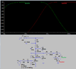
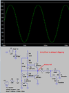
I simulated an amplifier with a fixed output 4 ohms resistor so that total speaker power can be seen.
I added a simple crossover network and it divided a woofer and tweeter to -3dB at 1kHz.
I feed equal levels of 150Hz and 5kHz.

With only the woofer and its inductor connected to the fixed output resistance of the amplifier I turned up the input level almost to clipping. (4.9V peak).
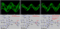
Then I connected the tweeter and its capacitor to show the output level dropping because the woofer and tweeter are basically in parallel and drawing more power, causing more voltage drop in the fixed 4 ohms output of the amplifier.
Then I turned up the input levels of both frequencies almost to clipping (4.2V peak) which is less than the 4.9V when the tweeter was disconnected.

Therefore the load is less than 8 ohms when the woofer and tweeter are both playing.
 

Attachments

  • Woofer and Tweeter frequencies.png
    Woofer and Tweeter frequencies.png
    28.9 KB · Views: 178
  • almost clipping.png
    almost clipping.png
    23.4 KB · Views: 170
  • crossover network.png
    crossover network.png
    64.2 KB · Views: 173
As you are using complex waveforms rather than a single sine wave, voltages are not a good measure of power. Measure the RMS current through the series resistor on the output.
 
I read all the members' discussion about my query, but still a solution is far away from now. All members should try to bring the right solution to my query so that I can make it successful. Please do it with your sheer experience.
 
I read all the members' discussion about my query, but still a solution is far away from now. All members should try to bring the right solution to my query so that I can make it successful. Please do it with your sheer experience.
Then tell us EXACTLY what you've got, so far it could be anything - give links.
 
Status
Not open for further replies.

Latest threads

New Articles From Microcontroller Tips

Back
Top