Continue to Site

Welcome to our site!

Electro Tech is an online community (with over 170,000 members) who enjoy talking about and building electronic circuits, projects and gadgets. To participate you need to register. Registration is free. Click here to register now.

  • Welcome to our site! Electro Tech is an online community (with over 170,000 members) who enjoy talking about and building electronic circuits, projects and gadgets. To participate you need to register. Registration is free. Click here to register now.

How to measure current ?

Status
Not open for further replies.

chanbkhn

New Member
Hi everybody !

I am building a project ( power supply , 5 V and I = 100 mA , I am a newbie ) I have a problem about measuring current .The first , I test current as figure

**broken link removed**

Measuring current is about 25 mA , then , I don't connect led , repeating measure current as figure ( about 30 mA )

**broken link removed**

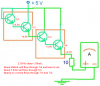
Because I want to have full current ( 100 mA ) , I connect series a darlington stage using a couple C1815 transistor as figure , after , I test current , but only 30 mA .I don't know what is happening ,althoght I connect three darlington stage , the current is very small ...I also add a darington ( using couple C535 ) into circuit , but the result is same ( about 30 mA )

**broken link removed**

My multimeter have error or my way is not good or ... , I don't know the reason and what must I do to solve this proplem ? I hope all my friends can help me solve this proplem .

Thank you very much !
 
Try with 100 darlington, you will get lower result :D
Reduce the resistance.
Is that a normal LED? You want to drive it with 100 mA? You need the base resistor too and you don't need a darlington, just a general purpose npn.
 
What you building a power supply?

The output circuit draws its own current that required to it.
If you build a power supply that can provide only 100mA, after you are connecting a LED to it. LED takes it own required current (according to the series resistor) not the whole 100mA.
 
It is not clear in the first two diagrams but the third diagram shows the resistor to be 10 ohms. I shall assume this is indeed correct. Now, in your first diagram, the highest voltage that can be across the resistor and LED is 5V-1.4=3.6V. The LED voltage drop is probably about 1.4 V so the remaining voltage across the resistor is 2.2V. In this case, you should be seeing 220mA flowing through the current meter. Yet, you only measure 25 mA. When you remove the LED (the second diagram), the current should increase to 360 mA. Yet you only measure 30 mA. In the third diagram, the voltage across the resistor is reduced to 2.2V yet you still measure 30 mA. The possible errors are:

- the resistor is not 10 ohms
- the 5V power supply is not able to deliver the current, and so it falls to some lower voltage when the circuit is connected
- the current meter is faulty or being used incorrectly

I would recommend to simplify the circuit to check where the problem is. I would remove the darlington feeding the resistor (by putting a short circuit from collector to emitter). If you do this, then your circuit is simply a 5V power supply across the series connection of 10 ohm resistor and current meter. You should measure 500 mA in this case, but the resistor will get very hot and possibly burn up. It would be better to use another resistor value so that you get 100 mA, which would require a value of 47 or 56 ohms. In this case the resistor will get hot but won't burn up as long as it is a 0.5 watt or bigger resistor.

This is a simple problem of ohm's law and if you don't measure the right current with the simplified circuit then there can be only two reasons. Either the power supply voltage is not 5V when the circuit is hooked up, or there is a problem with the current meter.
 
bananasiong said:
Try with 100 darlington, you will get lower result :D
Reduce the resistance.
Is that a normal LED? You want to drive it with 100 mA? You need the base resistor too and you don't need a darlington, just a general purpose npn.

Don't reduce the resistance because the value of resistor is 10 Om( not 10 K and 10 M ) ; it is small ...Is that a normal LED? yes , it is normal Led .I want to build out current ( I = 100 mA ) as figure , using led to only test . I don't connect led , add some darlington stage why are the results same ? my way is true or false ?

**broken link removed**

Yes , I try to use a general purpose npn .


Thank you !
 
Last edited:
To : @RadioRon and @Gayan Soyza
Thank all my friends , I try to do ...( according to tutorial ... )
Thank !
 
Do you want to test the Power Supply?

It appears that you have built a power supply with o/p voltage of 5V & current rating of 100mA. And now you want to test its performance.

To draw 100mA from 5V connect you will need to connect a 50ohms resistor directly to the output. You may use 47 ohms resistors which will draw 106mA. The wattage of the resistor works out to be W=V*I =0.5W, so use 47ohms/1w.

If you want LED indication, connect an LED with a series resistor of about 470ohms at the output. Similarly connect multimeter in DC voltage mode to the output & check that the output voltage does not drop below 5 volts.

Hope this will help

Sanjay Phirke
 
Hi,
Must it be 10 :eek:hm: resistor?
Try without any transistor and LED, just 5 V power supply and a 47 :eek:hm: resistor. You will get nearly 100 mA.
And, isn't driving a LED with 100 mA too much?
 
Load resistance must be take into account when dealing with small current applications.

Still chanbkhn didn't tell what he is going to make.So still we don't have a clear picture about it.
 
Last edited:
If the resistor is really only 10 ohms and the supply stays at 5V when it is loaded, then you have burnt out your little 2SC1815 transistor. It was trying to pass 268mA but its max allowed current is only 150mA.

The max allowed current in an ordinary LED is only 30mA so I think you burnt it out too.

Why are the transistors used as emitter-followers that waste voltage, instead of common-emitter?
Why so many transistors? A single transistor can easily switch only 100mA on and off.

Here is your circuit with the voltages marked:
 

Attachments

  • current meter.PNG
    current meter.PNG
    155.8 KB · Views: 308
Darlington & LED

Why do we have transistors in this project anyway? Are you sure your LEDs will handle 100mA? Most small LEDs are only good for 10 to 20mA.

I am using 100mA white LEDs that use about 3 volts. You should look at the data sheet and see what voltage to expect for 100mA. For a 5 volt supply, subtract 3 volts across my LED, leaves 2 volts across the resistor. (no transistor) Ohms lay 20 ohms = 2 volts/.1 amps. (1/2 watt resistor)

Darlingtons: Three transistors are ok but at about 4 transistors they tend to not work. (will not turn off)
 
Hi everybody !

I tried to do something ( according to the post ) and I understood what happened ,the components were damaged and the multimeter... After fixing these problem , I could measure current pass resistor and led , but the output current ...
I am building the circuit as the figure ( schematic ) , but I don't know how to measure properly the output current ( Iout )

**broken link removed**

The output current( no load , as the figure ) is max current , isn't it ?
Can I build the circuit with bigger the output current while the voltage is consant ?

Thanks all my friend !
 
Status
Not open for further replies.

Latest threads

New Articles From Microcontroller Tips

Back
Top