Fluffyboii
Active Member
Hello.
As some of you know I recently made a small AM transmitter. It made me really happy even though it has a range about 3 meters due to not optimal antenna and low power of it. I want to improve that transmitter by adding RF amplifier of some kind but I can't figure out a way to amplify a signal about 5-10V peak to peak with simple CE amplifier since high input voltage swing causes BJT to get out of active region and weak RF output of that circuit would probably drop from the input impedance of an RF amplifier and I am not qualified to calculate and compensate for all of that. My small research revealed me that RF transmitters and amplifiers are just an endless rabbit hole so unless I decide to torture myself by getting some RF classes I will not be able to fully understand and come up with stuff myself.
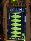
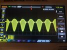
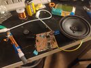
Anyway since I made the transmitter but only radio I have here is one that plugs into mains and hard to move I can not show it to anyone in action. I want to make a simple envelope detector radio receiver to go with it. I actually made something like that at a lab session with op amps but it was very bad since we used silicon diodes for detector and overall gain was very low so it required direct feeding of AM signal into the circuit and didn't had the capability of getting the small signal in the air. I wasn't satisfied at that time:

Book explanation of envelope detector:

I don't know my transmitter bandwidth but from its sound quality I am sure it is not 20Khz but something like 5-10Khz at best. My carrier freq is about 1.2Mhz which would mean for 10K detector resistor I would need a capacitor at least few pF. I don't have 5-10pF capacitors around and I don't think having a value that low can be reliable so maybe I need a lower resistance about 1K without passing to much current over the diode. Anyway I have Germanium diodes with about 0.3V drop and Schottky diodes that have around 0.2V drop for the job.
Input filter can be made with the 30pF-60pF variable capacitor I have and a 50uH inductor but range will be 1.3Mhz-900Khz according to my calculation. I would like to have the whole MW range in there but honestly there are no radio stations here to listen that broadcast MW so it doesn't matter. I can always 3D print a larger variable capacitor housing and cut some metal discs or make a large adjustable inductor if I get a reliable circuit going and want to improve on it.
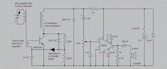
My real problem is the gain required and the finding antenna specs that are optimal. I saw many old, cheap MW radios that had 9 Transistors branding on them which is impressing to be honest. I honestly don't know how much gain I need but I assume at least 1000 since 100 gain doesn't even get close. I had this BJT amplifier with bootstraping at input to have a high input impedance here that has about 100 gain.

But since this is not a homework why wouldn't I cheat by using a mosfet at the input to have technically infinite input impedance. My only problem is that if I bias the mosfet with an voltage divider I would need to use very large resistance values about few megaohms to not load the weak input signal. I think I need something that biases the base with some kind of feedback network to avoid having a resistor to ground but I am not sure what is optimal here. Than after the mosfet buffer at the input I can have my 100 gain to feed my envelope detector than apply some more gain if needed. I will try to simulate it in LTspice. And at the last output buffer I can have a small toy speaker to hear the results. When I think about it the gate to emitter capacitance of the mosfet perhaps can be an issue. Cascode configuration was able to get rid of that miller capacitor and gave good gain perhaps it is a good idea to use it here.
For some reason whatever I tried I wasn't able to get and gain out of 2n7002 in LTSpice. I tried normal CS amplifier, I tried cascode with different configs, included perfect current sources for max gain but nope nothing got me gain more than 1. Maybe I am unable to see something in front of me since it is 5AM now and I used all of my mental resources. Added the LTSpice file. Unfortunately the one in the image with bootstrapping is lost.
I really can not get any transistor amplifier in LTSpice running now. Check Draft2 for example, there is no gain whatsoever. I don't know why maybe my LTSpice is broken.
I need to choose bias voltages more carefully. I totally forgot everything again.
As some of you know I recently made a small AM transmitter. It made me really happy even though it has a range about 3 meters due to not optimal antenna and low power of it. I want to improve that transmitter by adding RF amplifier of some kind but I can't figure out a way to amplify a signal about 5-10V peak to peak with simple CE amplifier since high input voltage swing causes BJT to get out of active region and weak RF output of that circuit would probably drop from the input impedance of an RF amplifier and I am not qualified to calculate and compensate for all of that. My small research revealed me that RF transmitters and amplifiers are just an endless rabbit hole so unless I decide to torture myself by getting some RF classes I will not be able to fully understand and come up with stuff myself.
Anyway since I made the transmitter but only radio I have here is one that plugs into mains and hard to move I can not show it to anyone in action. I want to make a simple envelope detector radio receiver to go with it. I actually made something like that at a lab session with op amps but it was very bad since we used silicon diodes for detector and overall gain was very low so it required direct feeding of AM signal into the circuit and didn't had the capability of getting the small signal in the air. I wasn't satisfied at that time:
Book explanation of envelope detector:
I don't know my transmitter bandwidth but from its sound quality I am sure it is not 20Khz but something like 5-10Khz at best. My carrier freq is about 1.2Mhz which would mean for 10K detector resistor I would need a capacitor at least few pF. I don't have 5-10pF capacitors around and I don't think having a value that low can be reliable so maybe I need a lower resistance about 1K without passing to much current over the diode. Anyway I have Germanium diodes with about 0.3V drop and Schottky diodes that have around 0.2V drop for the job.
Input filter can be made with the 30pF-60pF variable capacitor I have and a 50uH inductor but range will be 1.3Mhz-900Khz according to my calculation. I would like to have the whole MW range in there but honestly there are no radio stations here to listen that broadcast MW so it doesn't matter. I can always 3D print a larger variable capacitor housing and cut some metal discs or make a large adjustable inductor if I get a reliable circuit going and want to improve on it.
My real problem is the gain required and the finding antenna specs that are optimal. I saw many old, cheap MW radios that had 9 Transistors branding on them which is impressing to be honest. I honestly don't know how much gain I need but I assume at least 1000 since 100 gain doesn't even get close. I had this BJT amplifier with bootstraping at input to have a high input impedance here that has about 100 gain.
But since this is not a homework why wouldn't I cheat by using a mosfet at the input to have technically infinite input impedance. My only problem is that if I bias the mosfet with an voltage divider I would need to use very large resistance values about few megaohms to not load the weak input signal. I think I need something that biases the base with some kind of feedback network to avoid having a resistor to ground but I am not sure what is optimal here. Than after the mosfet buffer at the input I can have my 100 gain to feed my envelope detector than apply some more gain if needed. I will try to simulate it in LTspice. And at the last output buffer I can have a small toy speaker to hear the results. When I think about it the gate to emitter capacitance of the mosfet perhaps can be an issue. Cascode configuration was able to get rid of that miller capacitor and gave good gain perhaps it is a good idea to use it here.
For some reason whatever I tried I wasn't able to get and gain out of 2n7002 in LTSpice. I tried normal CS amplifier, I tried cascode with different configs, included perfect current sources for max gain but nope nothing got me gain more than 1. Maybe I am unable to see something in front of me since it is 5AM now and I used all of my mental resources. Added the LTSpice file. Unfortunately the one in the image with bootstrapping is lost.
I need to choose bias voltages more carefully. I totally forgot everything again.
Attachments
Last edited: