Continue to Site

Welcome to our site!

Electro Tech is an online community (with over 170,000 members) who enjoy talking about and building electronic circuits, projects and gadgets. To participate you need to register. Registration is free. Click here to register now.

  • Welcome to our site! Electro Tech is an online community (with over 170,000 members) who enjoy talking about and building electronic circuits, projects and gadgets. To participate you need to register. Registration is free. Click here to register now.

How to make a Momentary switch have multiple functions

Status
Not open for further replies.

djamfab

New Member
Hello,
I am pretty much new to the electronics scene. I am in the automotive industry and have been tuning EFI cars for a while now, but am starting to get into other aspects of the electrical system.
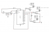
I want to make this:
**broken link removed**

**broken link removed**

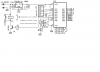
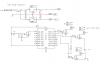
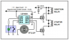
I guess what I am asking is how do you make a momentary switch have multiple functions? So the vehicle is Off, You push the button once and it is basically the run position of a keyed ignition switch... you push and hold the button and it engages the starter... release and the "run" position stays on... push it again and everything is off...
How do I do this?
Thanks!!,
Devin
 
You need a "state machine" (consisting of flip-flops) which defines the "next state" (new ones/zeros in the flip-flops) as a function of "present state" (present ones/zeros in the flip-flops) and "how long the button is pushed".

This can be built using discrete logic, e.g. flip-flops/gates, relays, or a micro-controller like a PIC16F84. Regardless of how you build it, you need to start by drawing a "state transition diagram" which defines the behavior. Google all the "quoted" things in this posting, and you will learn more than you ever wanted to know...
 
A microcontroller will handle this with ease. Try PICAXE for easy to program, very simple to use with plenty of support for beginners. And did I mention cheap??

weedpharma
 
if no programming experience then flip flops

a simple 7474 or even a 4017 might be easier.
google 4017 circuits then connect switching transistors to outputs then use relays.
couldn't be easier
 
can't believe $130 for that switch!!
just for fun I am going to play with this post and come up with a simple schematic and parts list
$130 do they wear bandannas when you buy this unit??
 
here is a basic circuit

not complete
push button = accessory on
2nd push=starter motor and ign
3 push = ing/run
no need to hold button for starter with this circuit.
might not be good ??
need to caculate resistor values based on coil resistance.
if wanting to hold pushbutton while starting then a PNP transistor comes into play
NOTE this is suggested schematic, needs work
 

Attachments

  • ign control.PNG
    ign control.PNG
    27.1 KB · Views: 1,656
Sometimes it would happen that you press once to get the ignition on and then change your mind and want it off because you forgot something in your home. Maybe 2 shorts pushs would be handy to reset the sequence to off. Other functions could be found easily, for instance 3 small pushs to get accessories only on.

Wy keep it simple when you can make it complicated?:)

(In whatever configuration there is a safety issue with this gadget. I believe there should be some kind of redundancy in the circuit.)
 
Last edited:
I agree

should also have some sort of security lock as well
If an LED display were incorporated then it coukd show which sequence you are on.
yes a PIC would be the better solution.
I recall on PCB Heaven he has a pic project called a clever switch.
it lights LEDs according to how you push the button
1 push = led1 comes on
2 short pushes = led2 comes on
hold briefly = led3 comes on
this code could be the basis for this vehicle starting system.
but does the op have the resources to program a pic.
be a fun project to design and build
 
basic pic schematics do not build as is

this is just the starting of this circuit ideas
needs a 4th press routine for accessories, combine the lock and clever button codes into one code and bigger pic


just need to use a bigger pic rework codes then only 1 pic would be needed
combo lock Electronic combination lock based on PIC

clever switch **broken link removed**
 

Attachments

  • pic combo lock.PNG
    pic combo lock.PNG
    45.5 KB · Views: 1,008
  • pic starter.PNG
    pic starter.PNG
    30.3 KB · Views: 880
I admit I'm curious too as to what it would take to reproduce that functionality. My choice would be a microcontroller (lol) with full press and release switch debounce, short and long switch press detection, along with new press beep feedback as well as a double-beep feedback at 1-second for a "long" press.

ignition-png.33762


Anyone want to see the software?

Regards, Mike
 

Attachments

  • Ignition.PNG
    Ignition.PNG
    15.5 KB · Views: 5,713
Last edited:
I like your operator feedback beeps

but why go with FET instead of simple transistors--just curious??
maybe by Sunday this circuit could reach a final design??
I think a combo lock is a requirement to prevent theft IMO
yes I know I didn't put diodes on the relays - just plain over-site
go ahead and throw some resistors at me ---lol
or better yet some PIC chips.
next circuit suggestions??
 
The "Clever Button" routine will not help you as it only illuminates a LED for 1 second and a lot of the coding is not shown.

However an 8 pin PIC is the answer and if you supply the exact requirements, a program can very easily be put together.
But you need to supply the exact details, fully explained in the minutest way, so the program can be generated.
The circuit suppled by Mike, K8LH is the best and transistors (Darlington) could be used for the output in place of FETs. But a speaker or piezo is handy to let you know what has been detected by the circuit and should be included.
 
Last edited:
the clever button needs rewriting

but the basic idea is maybe sound?
instead of the LEDs use relays and instead of the outputs going low after releasing the button, have the outputs remain high until another button sequence.
I havn't tried the clever button routine as of yet but all the code is not there?
it has a link to source files etc I think??
using the 8 pin PIC you can't integrate a keypad to lock the push-button so your ride doesn't walk away.
yes darlingtons may b the best choice.
maybe even a ULN2003 = all in one package??
I wonder where the pictured push-button was procured from?
 
MrDEB,

Here's the logic synthesized down into a simple ISR routine with speaker support removed to make it a little easier to understand (hopefully).

The first section of code is standard switch state logic to detect and filter state changes. The following code handles three different events. (1) On each "new press" we start a 1 second timer (the light blue vertical lines in the sketch). (2) If the 1-second timer times out during a 'long' press (the red vertical lines) we turn on the "starter" relay (active hi output) only if the "ignition" relay is on. (3) On each "new release" we turn off the "starter" relay after a 'long' press or toggle the "ignition" relay after a 'short' press.

Surprisingly short and simple, isn't it? Let me know if you want to see the version that supports speaker beep feedback.

Regards, Mike

ignition-logic-png.33774


Code:
void interrupt()                // 25 msec Timer 2 interrupts
{ pir1.TMR2IF = 0;              // clear Timer 2 interrupt flag
  swnew = ~gpio;                // sample active lo switches
  swnew &= 0b00010000;          // on GP4 pin
  delta = swnew ^ swold;        // changes, press or release
  newhi = delta & swnew;        // filter for new press bits
  newlo = delta & swold;        // filter for new release bits
  swold = swnew;                // update switch state latch

  if(tmr1sec)                   // if 1 second timer running
  { tmr1sec--;                  // decrement it and
    if(tmr1sec == 0)            // if timed out
      startpin = ignitpin;      // starter = ignition
  }

  if(newhi)                     // if new press
    tmr1sec = 1000/25;          // start 1 second timer

  if(newlo)                     // if new release
  { if(tmr1sec)                 // if 'short' press
      ignitpin ^= 1;            //   toggle ignition relay
    else                        // otherwise
      startpin = 0;             //   force starter off
    swledpin = ignitpin;        // update switch led
    tmr1sec = 0;                // clear 1 second timer
  }
}
 

Attachments

  • ignition logic.PNG
    ignition logic.PNG
    9.8 KB · Views: 5,046
Last edited:
I was thinking about that but

got sidtracked
a simple tach input would maybe do the deed.
 
ISR routine??

looking at your square wave, need to figure out what each tag is and compare to code you posted.
and what is with the 2 == in thrl loop??
 
MrDEB,

What are you referring to Sir? Oh, I think I know. In C a single "=" sign is an assignment operator so you use two "=" signs when you want to do a comparison.

Regards, Mike
 
Last edited:
If we light the push button LED from the PIC "ignition" pin we could use a 6-pin PIC.

Here's a quickly thrown together example program with much simplified switch state logic. The switch logic in the previous C program is better suited for multi-switch management and we just don't need anything that elaborate for a single switch. The program uses a loop instead of interrupts and it weighs in at a whopping 46 words of program memory. I'll post a version with speaker support later.
ignition-10f200-png.33887
Code:
;******************************************************************
;*                                                                *
;*  Filename: Ignition 10F200 v1.asm                              *
;*    Author: Mike McLaren, K8LH   (k8lh@arrl.net)                *
;*      Date: 30-Sep-09                                           *
;*                                                                *
;*                                                                *
;*  10F200 Ignition Switch Experiment                             *
;*                                                                *
;*                                                                *
;*     MPLab: 8.14    (tabs=8)                                    *
;*     MPAsm: 5.21                                                *
;*                                                                *
;******************************************************************

        include "p10f200.inc"
        list    st=off

        __CONFIG   _MCLRE_OFF & _CP_OFF & _WDT_OFF

        radix   dec

;--< hardware >----------------------------------------------------

#define ig_pin  GPIO,0          ; GP0 = ignition relay
#define st_pin  GPIO,1          ; GP1 = starter relay
#define spkr    GPIO,2          ; GP2 = speaker

;--< variables >---------------------------------------------------

        cblock  0x10
temp                            ; delay subsystem
swnew                           ;
swold                           ; switch state latch
tmr1sec                         ; 1 second timer
tmr25ms                         ; 25 msec timer
        endc

;--< macros >------------------------------------------------------

clock   equ     4               ; 4-MHz clock
usecs   equ     clock/4         ; cycles/usec multiplier

inDlyCy macro   pCycles         ; 0..1027 cycle range
        local   loop            ;
     if pCycles > 3
        movlw   pCycles/4       ;
loop    movwf   temp            ; 4-cycle loop
        decfsz  temp,W          ;
        goto    loop            ;
     endif
     if pCycles%4 >= 2
        goto    $+1             ;
     endif
     if pCycles&1 == 1
        nop                     ;
     endif
        endm

;******************************************************************
;
;  main program
;
        org     0x000
start
        movwf   OSCCAL          ;
        movlw   b'10011110'     ; 10011110
                                ; 1-------, IOC off
                                ; -0------, weak pullups on
                                ; --0-----, T0CS source Fosc/4
                                ; ---1----, T0SE edge hi>lo
                                ; ----1---, PSA prescale WDT
                                ; -----110, PS prescaler 64
        option                  ;
        movlw   b'00001000'     ;
        tris    GPIO            ; GP3 input, all others outputs
        clrf    swold           ; clear switch state latch
;
;  swnew  __---__---__---------__---__----------____
;  swold  ___---__---__---------__---__----------___
;   gp0   _____-----_____________-------------------  'ignition'
;   gp1   ________________________________------____  'starter'
;
sample
        movlw   25              ; prep 25-msec counter/timer
        movwf   tmr25ms         ;
        inDlyCy(1000*usecs-4)   ; delay 1 msec minus 4 cycles
        decfsz  tmr25ms,W       ; 25 msec sample interval?
        goto    sample+1        ; no, branch, else
        comf    GPIO,W          ; sample active lo switches
        movwf   swnew           ; save it
newpress
        btfsc   swnew,3         ; if swnew == 1
        btfsc   swold,3         ;   if swold == 0
        goto    newrelease      ;
        bsf     swold,3         ; update 'swold'
        movlw   1000/25         ;
        movwf   tmr1sec         ; start 1 second timer
newrelease
        btfss   swnew,3         ; if swnew == 0
        btfss   swold,3         ;   if swold == 1
        goto    timeout         ;
        bcf     swold,3         ; update 'swold'
        movf    GPIO,W          ;
        andlw   b'11111101'     ; turn GP1 'starter' off
        movwf   GPIO            ;
        movf    tmr1sec,W       ; a "long" press?
        bz      timeout         ; yes, branch (done), else
        clrf    tmr1sec         ; turn timer off and
        movf    GPIO,W          ;
        xorlw   b'00000001'     ; toggle GP0 'ignition' pin
        movwf   GPIO            ;
timeout
        movf    tmr1sec,W       ; 1 second timer running?
        bz      sample          ; no, branch, else
        decfsz  tmr1sec,F       ; is it timed out?
        goto    sample          ; no, branch, else
        movf    GPIO,W          ;
        btfsc   ig_pin          ; ignition on? no, skip, else
        iorlw   b'00000010'     ; turn GP1 'starter' pin on
        movwf   GPIO            ;
        goto    sample          ;

;******************************************************************
        end
 

Attachments

  • Ignition 10F200.PNG
    Ignition 10F200.PNG
    21.2 KB · Views: 5,644
Last edited:
Status
Not open for further replies.

Latest threads

New Articles From Microcontroller Tips

Back
Top