Continue to Site

Welcome to our site!

Electro Tech is an online community (with over 170,000 members) who enjoy talking about and building electronic circuits, projects and gadgets. To participate you need to register. Registration is free. Click here to register now.

  • Welcome to our site! Electro Tech is an online community (with over 170,000 members) who enjoy talking about and building electronic circuits, projects and gadgets. To participate you need to register. Registration is free. Click here to register now.

how to initialize LCD 16x2

Status
Not open for further replies.
And you've still not told anyone what your LCD data lines are connected to. Answer the questions asked and you might progress. Do you even know if you're using 8 bit or 4 bit mode?

Mike.
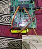
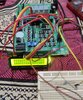
post #19 second image show the lcd data line connected to mcu

LCD -MCU

VSS - GND
Vcc- 5V DC
VEE- GND (potentiometer)
RS- RC4
RW- RC5
EN- RC6
D4- RD4
D5- RD5
D6- RD6
D7- RD7
LED+ - 5V
LED- - GND

I want use 4 bit interface mension in post #4
 
Looks to me like the cont pin is connected to GnD... Can you check the voltage on the CONT pin

Only if I know the board!! How else does it show the high nibble?
It says on the connector..
 
1601908798176.png


40 pin chips are all like this.... Port RC and RD
 
I have got source code from other forum member when I run code data display on the screen with black boxes I have adjusted pot but still problem is there

IMG_20201006_103607.jpg


source code attached
 

Attachments

  • 18F45K80_DEV-201_LCD_MCC_v540.zip
    31.2 KB · Views: 168
Last edited:
Well you can clearly see the text on that picture - it just needs the contrast adjusting, and the massively overbright LED's turning down - add a series resistor in the wire feeding the LED's to drop the LED current.
 
Can you tell me how many ohm registers to connect which pin

From your post #21, LED+ - 5V

The value depends on the exact display, and how bright you want the back light - I use 180 ohm on one of our manufactured products (it was originally lower than that, but then they updated the displays and they became brighter). So it's not critical, put in what looks best - try 82 ohms up to 200 ohms or so. At the moment, with no external resistor, you're running them as bright as possible.

I have tried resistors from 87, 95, 220 that decrease light of lcd

LED + resistor - board ground

I am very surprised because I do not understand what is happening, When viewing from one angle, the data is visible in the LCD and when viewed from the other angle the data is not visible in the LCD.

Attached screenshot
 

Attachments

  • IMG_20201006_150529.jpg
    IMG_20201006_150529.jpg
    723.8 KB · Views: 196
  • IMG_20201006_150451.jpg
    IMG_20201006_150451.jpg
    670.4 KB · Views: 184
I have tried resistors from 87, 95, 220 that decrease light of lcd

LED + resistor - board ground

I am very surprised because I do not understand what is happening, When viewing from one angle, the data is visible in the LCD and when viewed from the other angle the data is not visible in the LCD.

The viewing angle is quite small on LCD modules, you need to view from straight on, and adjust the contrast accordingly - by setting it a little too high you can increase the viewing angle a little, but then the background shows up, as in your pictures.
 
The viewing angle is quite small on LCD modules, you need to view from straight on, and adjust the contrast accordingly - by setting it a little too high you can increase the viewing angle a little, but then the background shows up, as in your pictures.
I have doubts, can this problem be caused by faulty code? I mean the problem is caused because lcd is not properly initialize
 
You can see characters so your problem is either contrast or brightness. Adjust them.

Mike.
 
I've normally found just connecting the V0 to Gnd is good enough. Disconnect the LED and it should look fine.

Mike.
 
Status
Not open for further replies.

Latest threads

New Articles From Microcontroller Tips

Back
Top