Pax Writer
New Member
Hi all
I've built a couple of projects which involved photo cells, and so far, I've just used an IR-led with a current-limiting resistor as a light source and a photo transistor with a pull-up as the light sensor - Sometimes with a buffer before the processor and sometimes without one.
This works okay, however, I made a test-bench where I had a propeller spinning through the photo cell, and I noticed that at around 100Hz, the circuit started having problems and the counter display attached showed spontaneous counter resets or no counting at all. This did not occur at lower frequencies.
Since the processor runs at 8MHz, it shouldn't have any problems keeping up. Nor should the display, as it consists of 7-segment displays driven by 4511s.
So I suspect the design of the photo cell needs optimisation, and I was hoping some of you users would advise me a bit.
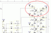
I have attached a snip of schematic containing the cell.
What would you change, and why?
I've built a couple of projects which involved photo cells, and so far, I've just used an IR-led with a current-limiting resistor as a light source and a photo transistor with a pull-up as the light sensor - Sometimes with a buffer before the processor and sometimes without one.
This works okay, however, I made a test-bench where I had a propeller spinning through the photo cell, and I noticed that at around 100Hz, the circuit started having problems and the counter display attached showed spontaneous counter resets or no counting at all. This did not occur at lower frequencies.
Since the processor runs at 8MHz, it shouldn't have any problems keeping up. Nor should the display, as it consists of 7-segment displays driven by 4511s.
So I suspect the design of the photo cell needs optimisation, and I was hoping some of you users would advise me a bit.
I have attached a snip of schematic containing the cell.
What would you change, and why?