Continue to Site

Welcome to our site!

Electro Tech is an online community (with over 170,000 members) who enjoy talking about and building electronic circuits, projects and gadgets. To participate you need to register. Registration is free. Click here to register now.

  • Welcome to our site! Electro Tech is an online community (with over 170,000 members) who enjoy talking about and building electronic circuits, projects and gadgets. To participate you need to register. Registration is free. Click here to register now.

How to fix CAN Bit Stuffing Error

Status
Not open for further replies.

jani12

Member
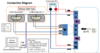
Our ADAS Controller is based on Renesas RH850/U2A16 Microcontrollers. We are using Infineon TLE9255WSK Partial Network CAN Transceivers. We are using Vector CANoe Professional.

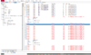
When a CAN message is transmitted on CAN Channel 2 from our controller to Vector CANoe, there is Bit Stuffing Error. Please see attached filename Bit_Stuffing_error_CAN_Trace.PNG.

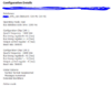
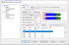
Also, attached are files that show our Vector CANoe tool configuration.

We are using 120 Ohms termination resistor.

What might be the problem? Is the problem in Vector CANoe Tool configuration? Or is this problem in CAN Driver source code in our controller?
 

Attachments

  • Bit_Stuffing_error_CAN_Trace.PNG
    Bit_Stuffing_error_CAN_Trace.PNG
    299.3 KB · Views: 2,228
  • Vector_CANoe_Pro_Configuration.PNG
    Vector_CANoe_Pro_Configuration.PNG
    76 KB · Views: 1,885
  • Vector_CANoe_Pro_NW_HW_Configuration.PNG
    Vector_CANoe_Pro_NW_HW_Configuration.PNG
    96.7 KB · Views: 2,058
Do all the systems have a common ground connection?
It seems unlikely it would cause an exact repeatable error, but it's just something to check.
 
Why multiple senders might cause this problem?

Assuming senders are causing this problem, how to debug it?

The problem occurs with Two specific standard CAN Ids. One is transmitted on CAN 1 to Vector CANoe tool and the other is transmitted on CAN 2 by Vector CANoe tool.
 
Clock frequency / bit rate errors?

If the bit timing drifts enough, one device relative to another, that could cause many problems..
 
Conventional CAN and CAN-FD use different bit-stuffing rules.
Is everything setup to use the same mode?
 
A few points come to mind.

I assume that the Vector CANoe tool is only there for debugging. If so, the existing CAN busses should already have 120 Ohm resistors at each end of the bus, so you should not add another 120 Ohm resistor.

Bit stuffing is the addition of a bit of opposite polarity after 5 consecutive bits of the same polarity. It is dealt with at a very low level with the CAN engine inside the microcontroller. The transceiver doesn't take part in the logic of transmission.

You can get a bit stuffing error if two nodes try to send frames at the same time with the same IDs, and different data.

CAN-FD may be seen by a normal CAN receiver as having bit stuffing errors, because the timing of the data is different. If any nodes are transmitting at the wrong baud rate, that will be seen as frame errors, which may be bit stuffing errors.
Oscilloscope traces can be very revealing. During arbitration more than one node will be transmitting 0 at the same time. Frame acknowledgement results in a single bit 0 being transmitted by all the receiving nodes at the end of the frame. At these times, more than one node transmits a 0, and this will result in a larger voltage difference between CAN-L and CAN-H than when a single node is transmitting. An oscilloscope trace will show when different numbers of nodes are transmitting.

It is also possible to see the difference between the voltages produced by different nodes, especially if the transducers come from different manufacturers.

The Vector tools can only see 0 (dominant) or 1 (recessive).

cantrace.png


The green trace is the difference between CAN-H and CAN-L. The red and yellow traces are CAN-H and CAN-L. They are offset slightly, and the actual voltages of CAN-H and CAN-L are nearly the same during recessive bits.
 
Last edited:
Isn't there also a difference in CAN-FD between ISO and non-ISO mode that might look like bit stuff errors too?
 
>> Frame acknowledgement results in a single bit 0 being transmitted but all the receiving nodes at the end of the frame.
What about the receiving nodes at the end of the frame?

What are vertical settings(volts per division) for each of Three channels above?
 
>> Frame acknowledgement results in a single bit 0 being transmitted but all the receiving nodes at the end of the frame.
What about the receiving nodes at the end of the frame?
I had a typo. I meant "Frame acknowledgement results in a single bit 0 being transmitted by all the receiving nodes at the end of the frame."

What are vertical settings(volts per division) for each of Three channels above?
They are all 1 V per division. The zero marker are on the left.
Red is CAN-H. Recessive is 2.5 V or so, and Dominant is about 3.6 V if only one transducer is transmitting.
Yellow is CAN-L. Recessive is 2.5 V or so, and Dominant is about 1.5 V if only one transducer is transmitting.
Green is the difference between the two. Recessive is 0 V and dominant is around -2.2 V if only one transducer is transmitting.
I arranged it that way up so that the traces didn't overlap on screen.
 

I've just noticed that the bit stuffing can bee seen in action in this trace. Between 30 μs and 80 μs after the start of the frame, there isn't any data to send, so the values are zero, which is dominant. Every time that five zeros are sent, a single one is sent as a stuffing bit. Stuffing bits are needed five times at the start of data in this frame, and possibly a couple of times near the middle.
 
>> if only one transducer is transmitting
Do you mean if only one node is transmitting? What would be voltage levels if more than one node is transmitting?

If we created such waveforms for our CAN bus, will it help solve our bit stuffing error issue?
 
>> if only one transducer is transmitting
Do you mean if only one node is transmitting? What would be voltage levels if more than one node is transmitting?
The transducer is the IC that actually connects to the CANbus wires. The node is the entire electronic module. I referred to the transducers because the voltage levels depend on the characteristics of the transducer ICs, and little else.

On the oscilloscope trace, the larger amplitudes during arbitration and during acknowledgement show the larger amplitude. During arbitration there were probably two transducers asserting a dominant level. During acknowledgement, there may be as many as 10 transducers asserting a dominant level.

If we created such waveforms for our CAN bus, will it help solve our bit stuffing error issue?
I thinks so. You certainly need more detail than the Vector equipement can provide.
 
>> You certainly need more detail than the Vector equipment can provide.
I believe your setup has One CAN bus. Above waveform are measured on One CAN Bus.
I believe in our setup we have Two CAN Busses. 1) CAN 1 Transducer is connected from our embedded controller to Vector CANoe. 2) CAN 2 Transducer is connected from our embedded controller to Vector CANoe. If these are two separate CAN busses then I should measure waveforms on both CAN busses?

Also, since we have Two CAN busses, do we need Four termination resistors?
 
A diagram would be helpful.

Vector CANoe devices will be use to fault-find CAN buses, so a bus has to work with our without the Vector CANoe. The normal arrangement is a number of CAN nodes, at least two, on a twisted pair of wires, and a 120 Ohm resistor at each end. Along the wire there can be any number of nodes.

The Vector CANoe will just be one of the optional nodes on the bus.

The Vector CANoe devices will often have multiple ports so that they can fault-find multiple buses at the same time, because many cars have multiple CAN buses. However, it you have just one bus to fault-find, you just connect to one port of the Vector CANoe device.

If you had two buses, with CAN 1 transducer connected to one port of the Vector CANoe, and CAN 2 transducer connected to the other port, you would need four resistors. However, the system would not connect anything if the Vector CANoe device were removed.
 
Status
Not open for further replies.

Latest threads

New Articles From Microcontroller Tips

Back
Top