Electro Tech is an online community (with over 170,000 members) who enjoy talking about and building electronic circuits, projects and gadgets. To participate you need to register. Registration is free. Click here to register now.
Welcome to our site! Electro Tech is an online community (with over 170,000 members) who enjoy talking about and building electronic circuits, projects and gadgets. To participate you need to register. Registration is free. Click here to register now.
I have got one of those small crystals, packed in a silver package, low-profile, two pins. How do I connect it so that I get the output that is printed on it (7,680)?
It sounds like you are looking for an AC output at the crystal frequency so the crystal is only part of an oscillator. Crystals can also be used in filters.
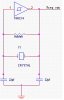
w00t!? Don't they need power or anything? Just the crystal, a resistor and an inverter gate, and then I get my square 7,68Khz output?? That looks way too simple and mystic!
w00t!? Don't they need power or anything? Just the crystal, a resistor and an inverter gate, and then I get my square 7,68Khz output?? That looks way too simple and mystic!
What would they need power for? THink of it.. it is just a piece of.. well crystal. There are no active circuits involved inside the crystal. The output power avalilable from the oscillator (not xtal) is from the inverters that sebi has shown.
A crystal by itself is a passive device of sorts. It only reacts to a stimulation input.
w00t!? Don't they need power or anything? Just the crystal, a resistor and an inverter gate, and then I get my square 7,68Khz output?? That looks way too simple and mystic!
This site uses cookies to help personalise content, tailor your experience and to keep you logged in if you register.
By continuing to use this site, you are consenting to our use of cookies.