pkshima
Member
Just finished fabricating the inchworm + on a breadboard. after much struggle, mplab is successfully connecting and os download went ok.
anyways, what I am now wondering is how to add a 40 pin zif socket to it so that i can use it as a simple programmer untill i grow up to in-circuit debugging etc.
sorry for noob question. I am just another sw guy so got all confused with the 'pull-up' stuff in the Target PIC Notes of the inchworm plus assembly guide.
Edit : I have also looked at the firefly instructions and schematic but I dontr have th brains to extract the circuit that just converts the ICD connection to the zif socket. especially where does the MCLR connection come from.
Last edited:
 . I think I am asking a simple question in the wrong way. so heres the question again
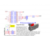
") perfect. This is what I was looking for. hope to see the led blinking finally.
perfect. This is what I was looking for. hope to see the led blinking finally.