Continue to Site

Welcome to our site!

Electro Tech is an online community (with over 170,000 members) who enjoy talking about and building electronic circuits, projects and gadgets. To participate you need to register. Registration is free. Click here to register now.

  • Welcome to our site! Electro Tech is an online community (with over 170,000 members) who enjoy talking about and building electronic circuits, projects and gadgets. To participate you need to register. Registration is free. Click here to register now.

how is output voltage calculated in LPF

Status
Not open for further replies.

ravi17

New Member
Hi,

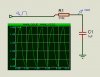
can someone explain why the output voltage of the following circuit is showing near +5V? the input signal is pulse signal of 5V and 0V. After the resistor there should be voltage drop and from my calculation the output voltage should be somewhere near 2.5V for high duration.

**broken link removed**
 

Attachments

  • 1.jpg
    1.jpg
    52.1 KB · Views: 216
hi 17,
As there is no resistive load across the cap to discharge the cap, it will charge to 5v, assuming that the 5v source impedance is high.
E
 
thanks

edit:
i connected a load resistor of 1Ohm and 10Ohm across capacitor but the voltage there is just micro volt range!
 
Last edited:
You have a voltage divider with a 300k and 100r resistors. Microvolts is what you should get.

Mike.
 
thanks mike

one confusion i want to clear up. i assumed and calculated the voltage divider rule by applying reactance of the capacitor Xc = 1/wC which is in parallel the the 300k res(with or without the load). so should the capacitor reactance not be applied in the calculation?
 
hi,
What is the frequency of the square wave input.?
E
 
32.png
 
hi eric, the frequency is 0.5Hz.

Mike, the resistor R2 should be at the load, after the capacitor, i guess, because the R1 and C are designed for LPF for 0.5Hz. correct me if i am wrong. also i didn't understand why cap reactance is not taken into account while calculating the output voltage using voltage divider rule!!
 
i didn't understand why cap reactance is not taken into account while calculating the output voltage using voltage divider rule
Because reactance varies with frequency.
A square-wave is composed of many frequencies in the frequency-domain, as shown by its Fourier transform components, so it does not have a single reactance for the square-wave signal.
So for such signals you normally use a time-domain analysis, not a frequency domain.

You would take reactance into account if you were doing a frequency-domain analysis with a single-frequency sine-wave.
 
hi eric, the frequency is 0.5Hz.

Mike, the resistor R2 should be at the load, after the capacitor, i guess, because the R1 and C are designed for LPF for 0.5Hz. correct me if i am wrong. also i didn't understand why cap reactance is not taken into account while calculating the output voltage using voltage divider rule!!

The load R2 is part of a voltage divider with R1. The filter is calculated by first combining R1 and R2 (Rt= R1*R2/(R1+R2) using Thevenin's theorem. The voltage is based on the voltage divider R2/(R1+R2). Finally, you calculate the cut-off frequency by finding where Xc1 = Rt.

The reason I drew the schematic the way I did was to remind you that R2 has to be considered first before worrying about C1.
 
Back to your original question in post #1:

32a.png


V1 has a duty-cycle of 50%. What would happen if it had a duty cycle of 10%? What would the average V(out) be then?
 
hi 17,
I did reply much earlier but my post disappeared, possibly due to the site software upgrade.
Using your posted plot, you can see the 2.5V point of the cap charging voltage occurs at 0.22Secs, as you would expect.
E
 

Attachments

  • v2.png
    v2.png
    40.3 KB · Views: 213
Status
Not open for further replies.

Latest threads

New Articles From Microcontroller Tips

Back
Top