Continue to Site

Welcome to our site!

Electro Tech is an online community (with over 170,000 members) who enjoy talking about and building electronic circuits, projects and gadgets. To participate you need to register. Registration is free. Click here to register now.

  • Welcome to our site! Electro Tech is an online community (with over 170,000 members) who enjoy talking about and building electronic circuits, projects and gadgets. To participate you need to register. Registration is free. Click here to register now.

How do you run a 3v-5v microcontroller from 6V efficiently?

Status
Not open for further replies.
I would like to use the minumum current possible to run a low power (mostly in sleep mode) PIC microcontroller.
I have a 6V (4xAA Alkalines) source, I could also use NiMH 5V (4xAA NiMH @ 1.25v) supply and trickle charge them at approx 1ma.

Any suggestions?

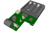
Oh yes; it's for the Armadillo lock on my site. Which is getting an I2C DS1307 RTC & 24LC256 EEPROM update at the moment
 
I'm sure others may have better suggestions, but I've been playing with this kind of thing myself. I would suggest either using the 4 nimh, or getting rid of one of the alkalines and run it regulatorless. I have been pretty surprised here. I have a 3.3v uC in a remote project here in sleep mode that I check every once in a while. It's running off a single 3v CR2032 coin cell battery, and it's been running for about a month.

Obviously this depends on the other power demands of your project, but if mine can run on a single coin cell for a month, you should be able to run with 4AA's for much much longer.

There are a few design rules to consider for reducing sleep mode power to the minimum. I think someone else listed them in a much earlier thread.
 
A CR2032 has about 210mAh @ 3v, a set of four NiMH cells would be 5v @ 2300mAh. I think I will use them unregulated with just a 1N5817 inline for reversal protection.
I plan to trickle charge the cells @ 1ma via a 4.7k pullup (the ibutton pullup) & diode 1N5817.
I've update the Armadillo .pdf schematic on my site with the trickle charging circuit.
 
Nimh batteries drain themselves substantially over a month, even with no load. If you are talking on the span of months at a time with a very little load, I think alkalines will actually last you longer.
 
I'm not sure I understand what you are trying to do though, if you have a circuit that will be constantly charging the batteries, why not just use that circuit as the power supply and ditch the batteries.
 
I think it's because of the high load that the motor will take. It looks like you are powering the lock motor off of the same supply. I would watch out for voltage drop when that motor kicks in. I'm not certain how large the motor is, but running motor and uC's off the same supply reuires a good circuit.
 
I thought it might be a simple way of keeping the NiMH batteries topped off, the only time the circuit needs any real current is when you power up the motor or solenoid. If the charger circuit proves useless I'll omit it.

The charging circuit uses the same wire pair as the 1wire communications driver option (at the other end with a 4.7k pullup to 5v) The idea is you can request the lock to close (1way communications) by toggling the state of a DS2405 1wire I/O. The make / break connector allows for a simple conductor cable to be used for the 1wire bus. A device similar to the OWL on myblueroom could be used although any iButton controller should function. The make / break also will tell a remote reader if the door is open (no DS2405 present).

There are many commercial locks with iButton readers

Much like this design at $628 US
**broken link removed**
 
The initial Armadillo was designed as a swap in replacement for the Weiser Digital Powerbolt (now owned by Black&Decker). The motor inside is a cheap 6v toy motor that drives a worm gear & clutch. It's only powered for about a second, there is a delay then it relocks. The Weiser only holds 2 combinations.

**broken link removed**

It's grown beyond that (although it would still be possible to use a subset of the schematic in a Powerbolt) (Rev E of the Armadillo will have an EXIT switch option in the schematic).
 

Attachments

  • powerbolt.png
    powerbolt.png
    75.1 KB · Views: 673
why not change your source to two or 3 AA's? that would provide 3 or 4.5V

and you can use resistors to limit current. Just use Ohms law to find out how current is calculated.
 
Status
Not open for further replies.

Latest threads

New Articles From Microcontroller Tips

Back
Top