Continue to Site

Welcome to our site!

Electro Tech is an online community (with over 170,000 members) who enjoy talking about and building electronic circuits, projects and gadgets. To participate you need to register. Registration is free. Click here to register now.

  • Welcome to our site! Electro Tech is an online community (with over 170,000 members) who enjoy talking about and building electronic circuits, projects and gadgets. To participate you need to register. Registration is free. Click here to register now.

How do I wire a vintage General Electrics motor

Status
Not open for further replies.

diatribe

New Member
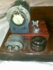
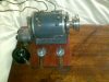
I recently purchased an IME lathe complete with a 1950's/60's General Electric motor and capacitor. The board the motor and lathe were situated on was a tad tatty, so I decided to make a new one. During the course of which I had to disconnect the wiring and made a diagram of where the three wires were attached. Unfortunately, this diagram was inadvertently discarded.

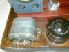
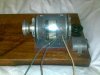
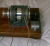
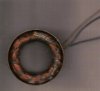
I would therefore be grateful for any advice on how to reconnect the wiring on the motor. I enclose images of the motor and capacitor situated on my new board. There are three wires emanating from the motor, the colours being brown, blue/green and yellowish light brown. The brown and blue wires have spade connectors which I presume are attached to the capacitor which has two posts, each with two connectors to take the spade connectors, but I don't know which one goes where. The other yellowish brown wire doesn't have a connector and I presume this is the live feed which connects to the switch, although I may well be incorrect with this hypothesis as it could be a neutral wire.


The data on the motor reads;-

General Electic,

Model.5KPM49FG166

HP 35M RP11 1600/1300 V.230

AO 25/ 0.31 CY 60/50 PH1

CAP. 1.5 MFD RUT CCW 0CV

Time Rating. CONT.


The capacitator,

68 12 60cy

Made in USA,

49E615 151

5UC 370V


I thank you in advance for any assistance that may be able to be afforded me on this matter.
 

Attachments

  • Image069.jpg
    Image069.jpg
    228 KB · Views: 156
  • Image071.jpg
    Image071.jpg
    336.1 KB · Views: 130
  • Image065.jpg
    Image065.jpg
    252.8 KB · Views: 208
  • Image064.jpg
    Image064.jpg
    82 KB · Views: 140
  • Image063.jpg
    Image063.jpg
    255.1 KB · Views: 131
Last edited:
You have no photo of wire ends? Wires usually have stake ons that slide onto the capacitor terminals. 3 wire motor is easy, wire that is not connected to the capacitor in 1 of the power wires. 1 of the wires on the capacitor is the other power wire. You have a white, black, green wire, I would say, white & black are the 2 power wires. Green goes to capacitor and 1 of the other wires go to capacitor too. It will not hurt anything to flip switch ON/OFF fast as you can see if motor runs. Try black wire on capacitor first if motor does not run then try the white wire on capacitor.
 
Last edited:
Hi Gary,
Firstly, thank you for taking the time to reply. I've taken another look at the wires in the daylight and taking into account fading, I can be more definitive on their hue. The colouring of the three wires are green, dark reddish brown and light yellowish brown. To simplify matters, I'll refer to them as green, brown and yellow.

The green and brown have spade connectors and the yellow wire is bare. I assumed that the green and brown wires must attach to the capacitor and the yellow to the live feed on the switch. I have made one attempt to wire the motor which culminated in blowing a fuse and decided I wouldn't make another attempt without seeking advice. I presumed that the yellow wire with the bare end must be the live feed and go to the switch, so I fitted a lead to the switch and connected the yellow motor wire to the live switch feed. I also had connected the green and brown wires to the capacitor(separately on each of the two poles.) Since then I have received some information indicating the light brown wire is in fact neutral, but if that is the case, where is the live feed coming from to start and run the motor.

''THIS MOTOR HAS A START AND RUN WINDING(TWO WINDINGS) AND A PAIRED NEUTRAL(LIGHT BROWN) HENCE THE THREE WIRES. IT REQUIRES A NON POLARIZED CAPACITOR (OF CORRECT RATING AND VALUE) INLINE BETWEEN THE DARK RED BROWN WIRE AND THE GREEN WITH EITHER SIDE CONNECTED TO LIVE WITH AN AC CAPACITOR IT DOESN’T MATTER WHICH..TABLES ARE AVAILABLE TO DETERMINE CORRECT VALUES.''

Before disconnecting the motor, I tested it and it was running fine, so the problem isn't with the motor or capacitor, its with my being electronically ignorant.
 
Last edited:
Quick question, do you have a meter which can measure the resistance between each of the wires?

There are a few possibilities here.
The motor has two windings, a start winding and a run winding,

IF these windings are identical then it does not matter which winding is used as start/run, the motor will just turn in opposite directions.

IF the windings are NOT identical, get it wrong and the magic smoke could be released! :eek:

If you have a meter, measure the resistances and let us know what they are.

JimB
 
Hi Jim,
I do have a meter, unfortunately, I don't really know how to use it and certainly wouldn't know how to measure resistances.(image enclosed. I can strip and repair complicated wristwatches, clocks et al, alas, anything relating to electricity most definitely ain't my forte

Can I make a start by assuming that the light brown/yellow wire that doesn't have a spade connector is the wire that goes to the live feed switch?.
 

Attachments

  • Image064.jpg
    Image064.jpg
    75.4 KB · Views: 112
OK, try this:

Turn the meter switch so that it is pointing down to the "200" position.
The display will probably show 1 . or 199.9
Touch the probes together, the display will show near zero. ( Ihave a similar meter which shows 1.0)

Now use the meter to measure the three wires as follows:
Green - Brown = ???
Green - Yellow = ???
Yellow - Brown = ???

JimB
 
Positioning the arrow on the meter at 200 on the bottom directly below off, a 1 is displayed. The readings between green and yellow after half a dozen readings are fairly constant at circa 64. The readings between yellow and brown are also fairly constant at circa 96. The readings between green and brown are wildly fluctuating between circa 40 and high 80's.

I have the black lead of the meter inserted in the black pole at the right hand bottom of the meter and the red lead inserted directly above it in the red pole reading 0.2A Max. fused. 1000VDC 750VAC. (There is another red pole above the aforementioned marked 10A DC)

Thank you again for your patience in helping me resolve this problem.
 
OK, a good start.
But...
The readings between green and brown are wildly fluctuating between circa 40 and high 80's.
That sounds like the connection between the probes and the wires is a bit intermittent, probably due to the wires being dirty.
Try gently scraping the wires to get them clean and measure again and let us know the reading on the meter.

JimB
 
Now we know for sure the 2 wires green & brown with the terminals connect to the capacitor and the yellow wire is the power wire. The only thing you don't know is where the other power wire = neutral connects? Put a 100 watt incandescent light bulb in the circuit like a power resistor connect to brown wire see if motor tries to run. If motor does not try to run on brown it will run on green. If motor tries to run on brown remove light bulb connect the other power=neutral wire to brown and motor will run. If you knew how to use a meter that might help. If you had a motor circuit drawing that would help. All the centripetal switch inside the motor does it remove the capacitor from the circuit at about 1000 RPMs. Centripetal switch is acting like a single pole double throw switch that drops out the start winding then connects the run winding above 1000 RPMs. Bring that motor to my house we will have it running in 2 minutes.
 
Inside the motor, the yellow and brown wire run together to the left side of the winding and the green wire runs separately to the right of the winding.(image enclosed) I don't know whether this is of any assistance. I actually worked for a company in the 1960's called Arco Rewinds, but I was not involved with the rewinding side, only metal spraying and skimming the coms on a Centre lathe. The company has long gone and I expect most of the staff are deceased.

Further readings with wires cleaned:-

Green-Yellow 64
Green-Brown 43
Brown-Yellow 97.9.
 

Attachments

  • Inner motor.JPG
    Inner motor.JPG
    108 KB · Views: 95
Last edited:
Inside the motor,
....I don't know whether this is of any assistance.
Yes it is. It shows that the motor is a simple "capacitor run" type, rather than one with a start winding switched by a centripetal switch as postulated by gary350 above.


So based on your latest measurements, try connecting it like this:
Lathe Motor Connection.png

Once you have it all connected up, I suggest that you run the motor for 30 seconds or so, and check that it is not getting excessively hot.

It would be a wise precaution to connect the body (frame) of the motor to earth, ie the green/yellow wire in the mains cable.

JimB
 
Note that is you connect the neutral to the wrong side of the capacitor, the motor will probably run the other (or wrong) direction.
 
Note that is you connect the neutral to the wrong side of the capacitor, the motor will probably run the other (or wrong) direction.
A good point, I agree.

I was thinking that because the two windings were of unequal resistance, it would be better to connect the higher resistance winding across the mains, and the lower resistance winding in series with the capacitor, thus minimising the current in the windings.

Having said that, it could be that the motor was intended to use the low resistance winding as the "main winding", and the higher resistance winding as the phase shifting start winding.

I think that my initial suggestion is the safe option, but if the motor turns in the wrong direction (Is the direction of rotation marked on the motor body? We do not know.) then it is a simple task to move the neutral from the yellow wire to the brown wire.

JimB
 
The following are all the markings on the motor other than those supplied with the identification plate

Directly under the General Electric identification plate, it is stamped Fort Wayne Ind. NP 205962 A8 Made in USA.

On each end plate it is stamped 4 BI

Between the fins on each end of the com, it is stamped 1 2 3 4 T 640 AK AN.

Com.JPG
Motor body ends.JPG
 
OK, but have you wired it up and does it run? (In the correct direction).

Enquiring minds are eager to know.

JimB
 
I was thinking that because the two windings were of unequal resistance, it would be better to connect the higher resistance winding across the mains, and the lower resistance winding in series with the capacitor, thus minimising the current in the windings.

JimB

As a general rule the lower resistance winding is the main run winding.
Max.
 
As a general rule the lower resistance winding is the main run winding.
OK, I can appreciate that.
Your motor fu could easily be greater than mine.

JimB
 
Without wishing to appear obtuse(where's the embarrassed emoticon) I don't understand the diagram. For instance, the only wire that can go the mains switch is the yellow wire and if that is going to neutral, where is the live feed coming from. The brown and green can only go to the capacitor, because of their spade connectors. The diagram is showing the green going to live, but as previously stated, it can only go to the capacitor because of the spade connection.

Of the three wires, the only one that can go to the mains switch is the yellow. Surely there has to a live and neutral connected to the aforementioned. With there only being three wires with two of them going to the capacitor, that only leaves one to go to the switch and the diagram appears to display the yellow wire as being neutral. I understand about switching the green and brown wires on the capacitor if the motor is running backwards, but I don't understand where the power to run the motor is generated from if there's only one wire(the yellow) to the mains switch, particularly in the vein that it appears to be going to neutral

I do appreciate its difficult trying to explain technical terminology to a person who has no knowledge on a particular subject. A similar analogy would be my attempting to explain the workings of a grande complication wristwatch to a person who doesn't understand the difference between a balance staff and a third wheel:)
 
OK try this:

The motor needs two connections to the mains, live (the brown wire in a mains cable), and neutral (the blue wire in a mains cable).

It is usual to put the switch in the live wire. You could put it in the neutral, but for various reasons it is much safer in the live wire.

An AC motor does not care which way round it is connected, it will turn in the same direction which ever side is connected to live and neutral.

So what I intended was this:
Lathe Motor Connection V2.png


Talking technical, for the other members here who are reading this,
how I show the connection to the capacitor, puts it in series with one of the two motor windings, thus creating a phase shifted current through one of the windings, which is what an induction motor needs to enable it to start.

Connecting the capacitor to the motor brown and green wires, puts it in parallel with the winding and does nothing to create the phase shift required to start the motor.

Does anyone here agree with me?


An afterthought.
It could be possible for the parallel connection to create a phase shifted current in the other winding so allowing the motor to start.
But to me this is just a mistake which fortuitously works.

JimB
 
Status
Not open for further replies.

Latest threads

New Articles From Microcontroller Tips

Back
Top