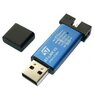
Hello everyone, I really need help in using STM32Cube IDE and TrueAtollic Studio. I have searched up and down on YouTube, and I haven't found a single good video on how to use these IDE's. I am using a STM32F030R8T6 and ST-Link V2 programmer (the image attached is exactly the one I have), there is a tutorial that uses this chip to learn ARM programming, but uses the CooCox IDE.
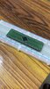
I made my own PCB, it is not a dev board, just converts the SMD chip to THT to plug it into a breadboard (image attached below). I would like help in getting me started to blink an LED using this MCU breakout board i have made all the way from the beginning from setting up the IDE and using the ST Link V2 programmer, with both Atomic studio and stm32cubeIDE.
If you know any good video/resource that explains how to use these IDE's clearly, please let me know. I am just a hobbyist, doing this for a project, out of passion, I would love to start using this chip to make amazing things,. It would be amazing if you could help me with this.
Thank you very much!
Attachments
Last edited:
