Continue to Site

Welcome to our site!

Electro Tech is an online community (with over 170,000 members) who enjoy talking about and building electronic circuits, projects and gadgets. To participate you need to register. Registration is free. Click here to register now.

  • Welcome to our site! Electro Tech is an online community (with over 170,000 members) who enjoy talking about and building electronic circuits, projects and gadgets. To participate you need to register. Registration is free. Click here to register now.

How do i remove noises in heartsound?

Status
Not open for further replies.

qkaifong

New Member
Hi all im doing a school project that requires me to capture heart sound, as close as it will be using a stethoscope.
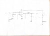
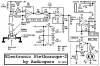
Im using invesense MEMS microphones analog ICS 40180, and LM358AP Op-amp. (I have attached a diagram of my connection)

I read from quora the frequency for heartsound is from 20Hz to 500Hz, I didn't have to exact resistor/capacitor values, so I'm capturing from 16Hz to 482 Hz.
(Do let me know if this range is wrong)
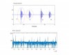
I have attached a picture of my signal that i captured and the signal i'm trying to achieve.

The signal i captured introduced a lot of noises, i have been trying different methods like putting capacitor in the power line, but it still did not remove the noise.
(I'm using 3V Battery)

How can i reduce/completely remove the noises?
Any help will be much appreciated, thank you!!
 

Attachments

  • diagram.jpg
    diagram.jpg
    61.3 KB · Views: 147
  • Waveform.jpg
    Waveform.jpg
    81.1 KB · Views: 126
What do you want this circuit to do?
It is not doing what you think it should.
Gain=? 100x maybe
Frequency response? 20 to 500hz if I remember right.
What do you want the DC bias to be? About 1V and why 1V?
119397
 
I'm making a non inverting amplifier that give a gain 100, because the mic pickup signal is too low.
If i did not include DC bias of 0.9V, whatever signal i picked up that fall below negative will be cut off.

Thank you so much for your fast reply!
 
How about this:
1) make Vref better. I think it should come from a real 1V voltage reference but 1k and 429 ohms is better than 1meg.
Added C3 to remove high frequency. I did not work out the right cap. (in my head)
119398


119399
 
Thank you for the detailed diagram, i will try it out.
Btw i see you have changed to ADTL084, will it still work if i were to use LM358AP still?

After output from opamp, capture signal and process it on Matlab.
 
i see you have changed to ADTL084
I did not have a LM358 to try. So I just picked something that I have a library for.
I would make Vref=1/2 supply or 1.5V.
The LM358; 3V supply is the smallest voltage it should work at. (warning)
capture signal
how? that is the question.

You probably understand C1R1 sets the low frequency cut off point.
C3R2 sets the high frequency point.
 
There is an app written for it for this project that allow me to record it in a tablet, then i will have to open up the text file in matlab to hear the recording.

I'm very new to working with Op-amp, and trying to learn as i go along.
What's the "warning" for?

And what is R4 for?
 
Last edited:
What's the "warning" for?
The warning is that you are using 3v supply on a device that has a minimum voltage of 3volts. If your batteries fall below 3v, your device stops working.
 
What's the "warning" for?
"supply voltage range 3V to 30V" Ok but you are on the edge.
"input voltage range" 0 to Vcc-1.7V So your Vref of 0.9V might be better than 1.5V as I said.
"output voltage range" with 10k load. Vcc-1.5V to near 30mV. Just saying you will not get a output near the 3V supply.
You might look at a "R-R output amp" They will work from supply to supply. R-R is rail to rail.
 
The LM358 is not used for low level audio because it is noisy (the hiss your circuit produces), it has crossover distortion and it has poor high audio frequencies output. I made an electronic stethoscope 15 years ago using a TL072 audio dual opamp and an LM386 audio power amplifier all powered from two 9V batteries. I used an ordinary electret mic, not a Mems one.
The audio opamp has low noise. The first opamp is a preamp with a gain of 22, the second opamp is a Sallen-Key active 2nd-order lowpass filter with a gain of 1.6 and the power amp is fed from a volume control and has a gain of 20. Today I would use an OPA2134 audio dual opamp that has less noise and a single 9V battery.

Your 1st-order passive lowpass filter does not do much so it passes the hiss.
 

Attachments

  • Electronic_Stethoscope_2 schematic.png
    Electronic_Stethoscope_2 schematic.png
    7.3 KB · Views: 115
Last edited:
Audioguru is yet another Legend that hangs out at ETO. There are many here. Sometimes legends get full of crap .... that is their right...ETO and it's moderators understand that. In fact, the Moderation here is superb. We here at ETO understand life. Most of here are are specialists in our chosen fields. As far as I am concerned, I trust ETO and it's advice 100% of the time.

I've been here around 9 years... never regretted a moment of it.

We're a class act. Team ETO. I don't post much Technical stuff cause noone really uses CRT anymore. So what I do is try bring smiles to Technical guys faces.

Once a tech always a tech.

That's me anyway. Naughty...comes the territory.

:) :) :)
 
something else you might want to try is using a small speaker as the microphone, and running it into a differential amplifier. speakers normally don't make good microphones because they only pick up low frequencies well. in your case that would be an advantage. the low impedance of the speaker will also help reduce electrical noise pickup, and the differential amplifier will only amplify difference between the speaker terminals, and reject most everything else.
119439


the speaker being used as a microphone would be connected across the V1 and V2 terminals. R1 and R2 should be equal, R3 and R4 equal, and the ratio of R3/R1 sets the gain.
 
Last edited:
The LM358 is not used for low level audio because it is noisy (the hiss your circuit produces), it has crossover distortion and it has poor high audio frequencies output. I made an electronic stethoscope 15 years ago using a TL072 audio dual opamp and an LM386 audio power amplifier all powered from two 9V batteries. I used an ordinary electret mic, not a Mems one.
The audio opamp has low noise. The first opamp is a preamp with a gain of 22, the second opamp is a Sallen-Key active 2nd-order lowpass filter with a gain of 1.6 and the power amp is fed from a volume control and has a gain of 20. Today I would use an OPA2134 audio dual opamp that has less noise and a single 9V battery.

Your 1st-order passive lowpass filter does not do much so it passes the hiss.
Hi my friend. I made this circuit. It amplify the sounds very good. But i cant hear the heart sound. What should i do?
 
The datasheet of the TDK Invesense MEMS microphone says that many of them have outputs that are digital, not analog. What is the part number of your MEMS mic?
We do not know how you attach the microphone to the chest, maybe skin is blocking the heartbeat sounds.
Will the amplifier or recorder and headphones or loudspeaker you are using produce the low frequencies of heartbeat sounds?
The signals gain of your opamp is only 100 times. Have you tried increasing it to about 1000 times? The gain of my circuit is 704 times and it works well.
I used electret mic with 2 pins (with top of bottle that the mic dont toch skin directly)
So i should increase op amp gain with
changin the resistors? But you know i think the gain of my op amp is good because i can hear the sounds of other thing very good.
 
Last edited:
The mic on its own will not do much.

You need to use an appropriate physical "coupling" to the microphone.

Think what the end of a stethoscope looks like..

Use a shallow dish or dome 25 - 30mm across, that touches the skin at the open side, with the mic fitted in a hole at the opposite side (like where the stethoscope tube would connect).
Put a membrane or diaphragm across the open side - eg. kitchen wrap "cling film" or a piece from a latex or nitrile glove or something similar, pulled tight and taped or glued around the outside.

That makes tiny movements of the skin against the membrane cause air pressure changes inside the dish / dome, which the microphone can then pick up.

Something like a plastic cap from a large-neck bottle could probably work well, with the edges sanded smooth so the membrane does not tear?
I used the top of bottle that my mic dont toch skin or chest directle.
 
Status
Not open for further replies.

Latest threads

New Articles From Microcontroller Tips

Back
Top