Continue to Site

Welcome to our site!

Electro Tech is an online community (with over 170,000 members) who enjoy talking about and building electronic circuits, projects and gadgets. To participate you need to register. Registration is free. Click here to register now.

  • Welcome to our site! Electro Tech is an online community (with over 170,000 members) who enjoy talking about and building electronic circuits, projects and gadgets. To participate you need to register. Registration is free. Click here to register now.

How do I implement a battery charger for a portable circuit

Status
Not open for further replies.

Smartie

Member
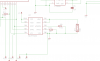
I've designed a LCD watch and had a simple battery charger that would charge the battery, but I overlooked the design and forgot to add a way for the circuit to be powered from the battery. (see schematic)

How to I make the circuit from the battery but also allow it to charge from usb when it's plugged in.

The cahrger (MCP73833) is a constant voltage and constant current charger (currents are selectable) and terminates the charge based on current.

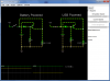
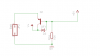
I thought about using a PNP transistor to disable the battery from supplying current to the circuit the moment USB is plauged in (See second schematic) It works in simulation and tested it with a battery pack and usb port. but I'm not too sure how it will work with the charger wired up to it as well.

Can you guys suggest ideas?

Cheers
Roman

The simulation can be seen here [Circuit Simulator Applet]
When the aplet loads, go File -> import and paste this
Code:
$ 1 5.0E-6 27.727228452313398 50 5.0 50
v 160 320 160 128 0 0 40.0 4.5 0.0 0.0 0.5
r 320 256 320 320 0 330.0
t 224 160 256 160 0 -1 -0.08750813957544867 -0.6446518966871473 100.0
r 224 208 224 320 0 1000.0
w 224 320 320 320 0
w 224 320 160 320 0
w 256 176 320 176 0
w 256 144 256 128 0
w 224 160 224 208 0
w 320 176 320 256 0
w 144 160 144 96 0
w 256 96 320 96 0
w 320 96 320 176 0
s 64 160 144 160 0 1 false
w 256 96 144 96 0
w 160 128 256 128 0
d 144 160 224 160 1 0.105904783
g 160 320 160 352 0
R 64 160 64 128 0 0 40.0 5.0 0.0 0.0 0.5
R 384 160 384 128 0 0 40.0 5.0 0.0 0.0 0.5
g 480 320 480 352 0
d 464 160 544 160 1 0.105904783
w 480 128 576 128 0
w 576 96 464 96 0
s 384 160 464 160 0 0 false
w 640 96 640 176 0
w 576 96 640 96 0
w 464 160 464 96 0
w 640 176 640 256 0
w 544 160 544 208 0
w 576 144 576 128 0
w 576 176 640 176 0
w 544 320 480 320 0
w 544 320 640 320 0
r 544 208 544 320 0 1000.0
t 544 160 576 160 0 -1 -0.08843971870554768 0.4115602812944523 100.0
r 640 256 640 320 0 330.0
v 480 320 480 128 0 0 40.0 4.5 0.0 0.0 0.5
x 147 78 324 84 0 24 Battery Powered
x 476 77 626 83 0 24 USB Powered
x 356 294 388 298 0 15 Load
x 593 293 625 297 0 15 Load
o 0 64 0 35 5.0 0.025 0 -1
o 37 64 0 35 5.0 9.765625E-5 1 -1
 

Attachments

  • battery.png
    battery.png
    22.6 KB · Views: 287
  • switch.png
    switch.png
    49.4 KB · Views: 216
Hi,


You have to tell us what kind of battery it is to begin with as some types of batteries are more difficult to charge than others, and you have to limit the current from the USB port to the battery during charge but even better build a small charging circuit.
 
Last edited:
Hi,


That kind of battery requires a special circuit to charge it. Did you ever build an electronics circuit before?
This circuit would not have to be too complicated.
 
Hey,

This is my first SMD Circuit but yes I have built electronic circuits before. The Li+ battery does have a special charger that's what the MCP73833 is.
I wasn't getting any responses so I went ahead with my idea (just two minor changes in the schematic resulted in only needing to solder two components onto the board) and my circuit worked!
It powers from the battery when the USB is not connected drawing an expected 50mA from the battery and when I plug in USB, the current draw drops down to -0.5mA as the charger would be trying to test the battery and the circuit works with out any problems.

A quick note. It's really hard trying to find a schematic or a article talking about live switching from battery to external power so that's why i wanted opinions on this.

I have attached a schematic of the circuit I'm using in case anyone else wants to use it in their circuit.
+5V - Power from USB
V+ - Goes to Voltage Regulator or your load
Batt.1 is Positive
Batt.2 = negative
the 10K is a pulldown resistor
the diode stops the Base of the transistor going high when the battery is running
The Transistor is a PNP in case you didn't notice =]

Cheers
Roman
 

Attachments

  • battery.png
    battery.png
    2.9 KB · Views: 263
Hi,

If I understand this correctly, you are trying to use the PNP to disable the battery while it is charging correct? If you entire watch is powered off of the battery then why not just connect all of the other components to the batteries terminals? It is a 1A charger and there should be plenty of power left in the circuit. I made a circuit a little like this for a radio of mine (that's still being put together), but in my design once power is applied to the circuit, then the battery monitor (your Lithium battery should definitely have one) disconnects the battery from the load as soon as charging power is applied. For my battery monitor I use an ICL7665, so to disable it, I used a 2N3906 PNP with a diode on the base connected to the main voltage supply, and a 10k resistor to ground. Like what your doing in your circuit (by the way, your diode is backwards).
 
Hey Dragon Trainer,

I thought my battery charger did disable the battery once external power was applied but when I tested it, didn't work. So that's why I cam up with the PNP transistor idea. Also I'm sure the diode is correct, if I reverse it, the USB wont be able to power the circuit

Cheers
Roman
 
Status
Not open for further replies.

Latest threads

New Articles From Microcontroller Tips

Back
Top