throbscottle
Well-Known Member
I've been playing with a design for a 4 wire ohms converter, and ended up with a simple ohms converter for force and an instrumentation amp for sense, which simulates beautifully for low values of resistance down to 0.1 ohms or lower, since the error can be offset at the in-amp's output, but it has an error due to leakage which at large values of resistance creeps up the scale. I'm looking at 6 digits of resolution and I'd really like the last couple of digits to be meaningful in the high resistance case.
Knowing that more errors will creep in in the real world, I'm trying to find the best compensation I can.
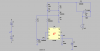
In the schematic, R5 is the DUT, R2 is the current-setting resistor, R3,R6,R7,R8 are the lead resistances, R9 and R10 are for automatic 2-wire/4-wire mode selection, R11 and R12 are to cancel the in-amp's input offset. The in-amp U3 will actually be an INA128 since TI are very kindly sending me a sample") so it's input bias current will be higher than that shown. The gain of the in-amp is unity.
so it's input bias current will be higher than that shown. The gain of the in-amp is unity.
V3 represents an presettable offset circuit consisting of an op-amp voltage follower and a preset potentiometer connected to a voltage reference
I tried connecting U1's + input to the in-amp's output instead of to R2, but it made the problem worse. Other feedbacks get complicated quickly.
The best solution I can think of is to make V3 sensitive to the current through the DUT so that it changes the offset with each setting - I know it's not true compensation, but it's a "good enough" solution without something better. The easiest alternative seems to be losing a couple of digits resolution, which I don't really want to do.
So my question is, what's the best way to implement a self-adjusting V3, and is there a better solution? Should I be looking at a current feedback amp here?
Thanks everyone in advance, and happy new year!
Knowing that more errors will creep in in the real world, I'm trying to find the best compensation I can.
In the schematic, R5 is the DUT, R2 is the current-setting resistor, R3,R6,R7,R8 are the lead resistances, R9 and R10 are for automatic 2-wire/4-wire mode selection, R11 and R12 are to cancel the in-amp's input offset. The in-amp U3 will actually be an INA128 since TI are very kindly sending me a sample
so it's input bias current will be higher than that shown. The gain of the in-amp is unity.V3 represents an presettable offset circuit consisting of an op-amp voltage follower and a preset potentiometer connected to a voltage reference
I tried connecting U1's + input to the in-amp's output instead of to R2, but it made the problem worse. Other feedbacks get complicated quickly.
The best solution I can think of is to make V3 sensitive to the current through the DUT so that it changes the offset with each setting - I know it's not true compensation, but it's a "good enough" solution without something better. The easiest alternative seems to be losing a couple of digits resolution, which I don't really want to do.
So my question is, what's the best way to implement a self-adjusting V3, and is there a better solution? Should I be looking at a current feedback amp here?
Thanks everyone in advance, and happy new year!