Continue to Site

Welcome to our site!

Electro Tech is an online community (with over 170,000 members) who enjoy talking about and building electronic circuits, projects and gadgets. To participate you need to register. Registration is free. Click here to register now.

  • Welcome to our site! Electro Tech is an online community (with over 170,000 members) who enjoy talking about and building electronic circuits, projects and gadgets. To participate you need to register. Registration is free. Click here to register now.

How could this be done with a Pic or Micro.

Status
Not open for further replies.

killivolt

Well-Known Member
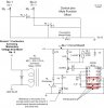
While sequence is happening a microphone is un-muted

Sequence :

1. Stu 1 pushes his momentary contact button at his desk.

2. Db Port 2 pin fires from the mixer to momentary contact.

3. Momentary relay closes RL/DPDT.

4. Master relay opens locking out other students.

5. Stu 1 relay closes, allowing for reset.

Student asks question or finishes statement.

6. Stu 1 pushes his momentary contact when finished at his desk.

7. RL/DPDT closes - RL 1 opens as well and "Master relay" closes.

Ready for sequence to begin for another Stu 1 or 2 or 3 or 4 Circuit board.

kv :)

Edit: Keep in mind the Microphones are 2 ceiling mount omni directional Mics.

It's breadboarded and it works.

I'll begin testing with few circuit boards together to see if I find any glitches.

But, in the future I would like to perform this with a Pic or pics and or a Large Microprocessor.

I need 12 inputs / and Maybe 2 outputs = I need to lockout all inputs except one. I need the output to trigger maybe a dual flip flop to supply one or two relay's. I think the associated Hi/low pins can produce a one shot either Active High or Active Low. Latching or momentary. ( I'm a newbie to this. For all my mistakes Please, forgive me.:eek:)
 

Attachments

  • Student Push Lockout Relay Review.jpg
    Student Push Lockout Relay Review.jpg
    43.6 KB · Views: 143
What modification other than the appropriate resistor would I have to make on this circuit to implement an led off the 2n3904. I'm thinking of driving a small one in between Coil and the diode 1n4148 on the collector.

Maybe it will throw the circuit out and change the 2.7k to another value or do I have to change both also on the collector.

Or you say don't worry about it the CD4013 won't have any trouble with it.


kv

Edit: typo - Transistor to "appropriate resistor"
 
Last edited:
You should label the parts R1, R2, etc because there are two 2.7K resistors, etc. But to answer your question, just change the 1n4148 (The one in series with the 2.7K) to a LED.
 
You should label the parts R1, R2, etc because there are two 2.7K resistors, etc. But to answer your question, just change the 1n4148 (The one in series with the 2.7K) to a LED.

Ok, I will. Plus I thought I could do that but that is a fast acting diode and thought it meant something to the circuit.

Thanks a bunch.


kv
 
The other 1N4148 diode (closer to the RL1 relay coil) actually does something. The 1N4148 and 2K7 series resistor were just wasting current so you may as well light a LED instead. ;)
 
Last edited:
Made reference to Resistors 2k7 added R1 and R2 helping identification. Added an LED to indicate which buttons have been activated and a Pb to act as an override in case 2 buttons are energize at the same time. Canceling 1 of them.


Thanks.

kv:)

Edit: Do you think I should kick up the amperage on the LED some more I'm about 8.5ma at the moment with 1.79vf.
 

Attachments

  • Student Push Lockout Relay Review.jpg
    Student Push Lockout Relay Review.jpg
    49.5 KB · Views: 126
Last edited:
You could kick it up to 15ma or so, depending on the LED. You won't notice much of a difference since your eye is logarithmic anyway. Going from a red to a green LED would be more noticeable since the eye is more sensitive to green.
 
You could kick it up to 15ma or so, depending on the LED. You won't notice much of a difference since your eye is logarithmic anyway. Going from a red to a green LED would be more noticeable since the eye is more sensitive to green.

I think I'll use an LED with a wider viewing angle. :)

Thanks

happy happy joy joy .:D


kv
 
Status
Not open for further replies.

Latest threads

New Articles From Microcontroller Tips

Back
Top