RacerX
New Member
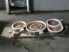
I bought a pole distribution transformer for my tesla coil project. It's a 15KVA 14.4kv 300 pound beast! The transformer runs off 240Vac. But it does not have current limiting. It essentially has no resistance across the primary coil. If I tried to plug it in I would essentially short out my house.
Any ideas on a VERY high wattage resistor? I was thinking about a heating element from an electric stove. But it's resistance would increase and the element heated up. I'm not really sure how many ohms it should be but I'm guessing 15-20ohms. Any ideas? Any links on some low cost 5KW resistors?
**broken link removed**
BTY, I know of the dangers of high current electricity. This is not my first project with high voltage. I've built a few tesla coils in the past.
-Tony

")
")
 Maybe you should have petted the neighbors dog and not his wife.

