Continue to Site

Welcome to our site!

Electro Tech is an online community (with over 170,000 members) who enjoy talking about and building electronic circuits, projects and gadgets. To participate you need to register. Registration is free. Click here to register now.

  • Welcome to our site! Electro Tech is an online community (with over 170,000 members) who enjoy talking about and building electronic circuits, projects and gadgets. To participate you need to register. Registration is free. Click here to register now.

High Voltage Capacitor charger

Status
Not open for further replies.
Hi everyone.

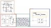
I was trying to built a high voltage capacitor charger circuit as a project. I have made a 12v DC to AC inverter at 55Khz using an IR2153 IC. With a centered tapped ferrite transformer and a full wave voltage multiplier (i use fast UF4007 Diodes) attached to IR2153 circuit, i can produce around 6kv output at 12v DC input. I have used an adjustable LM317 Voltage Regulator attached to the center capped primary coil in order to adjust the Vout, so it can be anything between 800v and 6kv. For about 2kv output, only 2.5v input are required. I have used an 1/100 Vdivider (40M resistance) in order to measure the High Voltage. I tried to charge x2 Microwave oven capacitors in series at 2kv. When 2kv reached (20v from the Voltage Divider) i tried remotely to discharge them into a thin copper wire to see if they where actually charged, but nothing was happened. Have you got any idea why did not worked ?

Thanks
 
Please post a schematic of your setup.
 

Attachments

  • 1.jpg
    1.jpg
    126.6 KB · Views: 487
What is "V/100"?
Do you have a volt meter there?
--edited---
You have high voltage via the meter but maybe no voltage on the capacitors? Interesting?
 
Yea that is my Vmeter. The V/100 is the voltage output from the Vdivider and it is 1/100. I do have high voltage but when i tried to discharged them nothing was happened. My volt meter was reading 20v so it was 2000v. It is very acurate,i have calculated the Vmeter internal resistance and i have check it with a battery reading milivolts. I used a 5 meters coaxial cable in order to discharge them to a thin copper wire.
 
Your schematic doesn't show any remote discharge arrangement. How was that done?
Are you sure your 40Meg divider wasn't breaking down and discharging the caps?
Can you post a pic of the actual divider used?
 
R1 is 40M. The sum of R2 and Vmeter is 404K in order to give 1/100. Internal resistance of Vmeter is 1M. I used a coaxial cable and some speaker wire. The switch was from a remote control relay like **broken link removed** one. Consider that Microwave oven caps do have a 10M bleed resistors each. So i was thinking if there is a possibility that the resistors (internal and Vdivider) don't let the caps to charge. Any idea ?
 
Have you considered that the amount of energy stored in the capacitors may not be enough to melt the wire. The energy stored in a capacitor is 1/2 C x V^2
So Your capacitance is 0.5 uf (2 x 1 uF in series.) 1/2 x 0.5/1000000 x 2000 x 2000 = 1 joule.

Les.
 
Due to resistors right ? If i remove the Vdivider should anything happened ? Note that the charging circuit is ON when i try to discharge them.
 
If the circuit is as your schematic, you are measuring the voltage directly across the capacitors.

Either they are charged when you read the voltage, or something does not match the schematic, or one or both the capacitors are faulty.
 
If the circuit is as your schematic, you are measuring the voltage directly across the capacitors.

Either they are charged when you read the voltage, or something does not match the schematic, or one or both the capacitors are faulty.

The circuit is like the schematic and it works as i can measure high voltage and adjust it as much as i like. Vdivider works well as i have tested on milivolt scale. Caps looks to work nice too cause when i close the circuit, it takes a while to get discharged. It is indeed very strange and i really did not expect something like that.
 
I just re-read the earlier posts, about trying to melt a wire.

The caps may just have too much internal resistance to discharge at high current. Drawing an arc may give a rather different result.
 
Ok after searching a bit on youtube i found that a guy have built an EBW circuit with 2 Microwave oven caps


So it is possible to charge and discharge them. It is almost what i tested but i my case nothing was happened.
 
I was thinking that maybe due to resistors, the capacitors can not be charged, and they actually only work out as a filter. My batteries can put out around 10A so at 3v and 10A there Is a 30w power. If voltage inverted to 2000v, the amp should be 0.015A at 100% efficiency (0.015x2000=30) So if resistors and multi-meter consume more current than 0.015A, they could not get charged right ? The internal resistors got 20M (10M for each capacitor) and the vDivider got 40.4M. How much current those resistors will draw ? If they could not get charged how i get the high voltage output from the Vdivider ?
 
Playing with capacitors charged to 6kV is not for the inexperienced. What rating are the capacitors?

Mike.
 
So if resistors and multi-meter consume more current than 0.015A, they could not get charged right ?

IF they were never getting charged, the meter circuit connected directly across them could never show any voltage!
That's why I asked earlier about the accuracy of the diagram etc.
 
Playing with capacitors charged to 6kV is not for the inexperienced. What rating are the capacitors?

Microwave capacitors are usually 2400vdc working, and just under 1uF (such as 0.91uF), although higher power ovens (800w rather than 700w) have slightly higher values than smaller ones. Commercial high power ovens generally just have two entirely separate lower power oven circuits inside - so two mags, two rectifiers, two capacitors, two transformers.
 
They are 2100v AC at 0.9μF


I use 2 of these


IF they were never getting charged, the meter circuit connected directly across them could never show any voltage!
That's why I asked earlier about the accuracy of the diagram etc.

The vdivider circuit is quite precise, for example, a battery that got 12.18v, with the Vdivider connected i will get close to 122mV. Maybe i will try to charge them again and when i got the value i want, i will disconnect the vdivider and try again. Maybe the caps are faulty too, who knows.
 
Last edited:
Status
Not open for further replies.

Latest threads

New Articles From Microcontroller Tips

Back
Top