Continue to Site

Welcome to our site!

Electro Tech is an online community (with over 170,000 members) who enjoy talking about and building electronic circuits, projects and gadgets. To participate you need to register. Registration is free. Click here to register now.

  • Welcome to our site! Electro Tech is an online community (with over 170,000 members) who enjoy talking about and building electronic circuits, projects and gadgets. To participate you need to register. Registration is free. Click here to register now.

High side pnp switch

Status
Not open for further replies.

drkidd22

Member
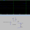
I have this high side p-channel switch that works ok if I was just driving the LED.
But in my case Vout is also being used to drive the control line of a solid state relay. My issues is that the relay does not go fully off because I still have output voltage on Vout even when M1 is supposed to be off. Is this due to the voltage forward of the LED?
 

Attachments

  • pnp_highsidesw.PNG
    pnp_highsidesw.PNG
    17.5 KB · Views: 177
  • HighSidePNPSwitch.asc
    1.1 KB · Views: 151
Where is the relay? From Vout to ground?
I added a 1k resistor from Vout to ground and all is well. I think you need to put the relay in the circuit and it will work. Remember to put a diode across the relay coil to stop the reverse voltage.
---------
Why do you have this problem? The LED passes no current when the voltage is less than about 2.4 volts. No current is to say R3 220 ohm resistor also has no current. There is nothing to pull Vout to ground. That is why the 1k resistor I added pulls Vout to ground. The relay coil will pull Vout to ground just fine.

1605841377159.png
 
Yes, loads are a few AC motors, heaters, and solenoid valves (similar repeated circuits).
I only found the problem because the solenoid valve was not shutting off completely when Q1 was off.
I'll give that a try next week thanks!.
 
As ronsimpson says, you need a resistor to ground.

The LED in the circuit diagram is large, with a rated current of 1.5 A, but it's being run at far less than that. The Vf of the LED at full current is more than the supply voltage, so it's difficult to estimate what current and Vf you'll get.

Is that the actual LED being used?

The reason that I'm asking is that the LED may be acting as a photocell and generating a voltage when it's illuminated. All LEDs that I've tested this on produce some voltage in the forward direction when illuminated, so current will actually flow through them in reverse in that condition. The voltage will always be less than Vf, but in this case it only needs 1 V for the PF240D25 to remain on, and virtually no current is needed.

There may be leakage from the transistor as well.

The waveform doesn't have a voltage scale, so I don't know how low the voltage is going, but it doesn't drop sharply. That indicates that there should be something to pull the voltage down to ensure that the PF240D25 turns off.
 
You've produced a floating voltage using the capacitance of the FET and the diode. As others have said a resistor to ground would solve it. The charge is so low it wouldn't have an affect on a relay so something else going on there. BSS84 has a 6ohm RDS so at 3.3v you've got 500mA maximum to drive the relay on, in theory. Closing in on this current value will leave nothing for the LED.
 
Last edited:
As ronsimpson says, you need a resistor to ground.

The LED in the circuit diagram is large, with a rated current of 1.5 A, but it's being run at far less than that. The Vf of the LED at full current is more than the supply voltage, so it's difficult to estimate what current and Vf you'll get.

Is that the actual LED being used?

The reason that I'm asking is that the LED may be acting as a photocell and generating a voltage when it's illuminated. All LEDs that I've tested this on produce some voltage in the forward direction when illuminated, so current will actually flow through them in reverse in that condition. The voltage will always be less than Vf, but in this case it only needs 1 V for the PF240D25 to remain on, and virtually no current is needed.

There may be leakage from the transistor as well.

The waveform doesn't have a voltage scale, so I don't know how low the voltage is going, but it doesn't drop sharply. That indicates that there should be something to pull the voltage down to ensure that the PF240D25 turns off.

No it's not the actual LED. I'm using a regular 0805 greed SMD LED (couldn't find one on LT default library).
I added the resistor and this fixed the issue with the input control line to the relay so this is now being driven correctly.
But I still see residual voltage at the output of the relay, for example AC line pin 1 (A) is 120VAC and AC line pin 2 (B) is ~38VAC when the relay is off.
I get the full 120VAC when it's on. This is open circuit testing, nothing on the load.
I'll put up the actual circuit schematic later.
 
If you are testing the output of an AC relay with no load, then what is happening is that you are getting capacitive coupling to the mains input. It's just another version of the first problem that you had where not connecting something to a supply is not the same as connecting something to ground.

A modern multimeter will pick up a voltage from being close to a mains wire. That doesn't mean that a real load will be powered, so if the load you intend to use takes more than a few mA, it will be turned on and off fine by the relay.
 
That's another possibility I've thought about.
What's bugging me is that every other inductive load (AC Motor, Fans) and resistive heaters work ok, the only one giving me issues is a fluid solenoid valve that doesn't close all the way when I turn the relay off. I can still hear the valve being energized, If I unplug the power cable to the solenoid it closes.
 

Attachments

  • Solenoid Valve mcmaster 2660K23.pdf
    810.8 KB · Views: 164
New idea.
Solenoid. Max load on the coil is 320mA but no one knows the minimum current. My solenoids, when closed draw about 300mA but when open draw much less. I do not remember how much less. 1/2 or 1/4 ??
Relay: Must see a load of at least 60mA! also Max power factor 0.5. I question of the relay will turn off if the load is low and very inductive.
Test: Lets test the idea. Put two solenoids in parallel and see if it works. Or put a load across the solenoid. Do something to increase the load.

This is almost what Diver300 is saying.
 
Here is the schematic.
I will try adding a load when relay is off to see what happens.
 

Attachments

  • ACControl.pdf
    148.3 KB · Views: 183
The solid state relays may well have internal snubbers; RC networks to limit voltage spikes from inductive loads.
Try fitting a separate snubber (eg. 0.1uF with 100 or 47 ohms) across the solenoid to bypass some of the capacitive leakage.
 
1. Why do you need R1?
2. I would have put the LED & relay on the drain rather than the source.
3. It may be possible to connect the LED in the relay in series with D2. So R3 should not be necessary.
 
New idea.
Solenoid. Max load on the coil is 320mA but no one knows the minimum current. My solenoids, when closed draw about 300mA but when open draw much less. I do not remember how much less. 1/2 or 1/4 ??
Relay: Must see a load of at least 60mA! also Max power factor 0.5. I question of the relay will turn off if the load is low and very inductive.
Test: Lets test the idea. Put two solenoids in parallel and see if it works. Or put a load across the solenoid. Do something to increase the load.

This is almost what Diver300 is saying.

I ended up adding a resistor across the solenoid coil. Now when the relay is off I get 0VAC across the coil and valve shuts off all the way.
When relay is on I get 210VAC across the coil and valve is open. I now think that because one of the lines is always at ~120VAC some how the valve had some residual current (which should go away eventually) that was keeping it from completely shutting off.
 
I think the load was too small and very inductive.
If it works, that is most important.
 
If there is a suppression capacitor across the relay, that can formed a tuned circuit with the solenoid. If you are unlucky, that will be tuned to mains frequency. The resistor will damp the tuning so it will be a big help.
 
Status
Not open for further replies.

Latest threads

New Articles From Microcontroller Tips

Back
Top