Continue to Site

Welcome to our site!

Electro Tech is an online community (with over 170,000 members) who enjoy talking about and building electronic circuits, projects and gadgets. To participate you need to register. Registration is free. Click here to register now.

  • Welcome to our site! Electro Tech is an online community (with over 170,000 members) who enjoy talking about and building electronic circuits, projects and gadgets. To participate you need to register. Registration is free. Click here to register now.

High Side Current Sensing

Status
Not open for further replies.

geobabu

Member
HI All,
I need to implement a high side shut resistor based current sensing with a Differential ADC. Here the line consists of around 12VDC @ current varies from 1 to 10A. Eventhough the drop stands within the Differential i/p voltage limit(+/- 2.048V), its common mode voltage is higher than what is allowed.
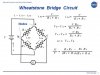
Also I am aware that, there are some dedicated ICs and Opamp based instrumentation amplifiers are available, I am just trying to implement with same ADC & less components (as shown in the attached image.) . Simulation everything seems good, but before implementing I am seeking some advice from you. Whether this is a good practice for implementation. Hoping for your valuable suggestions.
Thanks in advance
Regards,
Geo

ADC_current sense.JPG
 
hi geo,

Have you checked the CMV input range for the LM324.?

Its suitable for High side sensing.

E.

Please post your LTSpice asc file.
 

Attachments

  • LM324.pdf
    208.3 KB · Views: 376
Yes LM324 have a very high i/p voltage range of ~32V. Which is enough for normal cases. What I thought is just to eliminate the usage of an OPAMP, if the ADC direct interfacing as shown in the circuit is working. In simulation it seems fine, still confused regarding its implementation. No where I have seen such a kind of circuit for reference.
Thank you
Geo

LTspice file .
 

Attachments

  • Draft12.asc
    1.1 KB · Views: 240
hi,

With just a resistive 'bridge' the actual bridge output is low for a 10Amp current.

The 0.05R IMO is too high a value for a 10A sensor, at a load current of 10A you are 'losing' , 0.5V across the shunt.

I will look at the d/s for the diff ADC device.

E.

EDIT:
Looked at the MCP3422, why dont you use the example circuit shown in that data sheet.?
 

Attachments

  • AAesp01.gif
    AAesp01.gif
    18.9 KB · Views: 740
Yes, for 10A it will drop ~0.50V across it. Maybe we reduce the shunt resistor value for reduce the drop. In this case it can be adjusted.
In the application circuit, there are used it for the small battery sensing, whose common mode voltage is very less than its rated values. (Its mentioned in one of its App Notes.
The max. allowable voltage to its pins is
• Input voltage < VDD+0.3V
• Input voltage > VSS-0.3V

And ADC's sensing range is within the VREF (in this case a fixed internal VREF of 2.048V). So we can't give more than that. In the differential mode , the input voltage range should be within +/- 2.048V
–VREF ≤ (VIN • PGA) ≤ (VREF – 1LSB)
Where:
VIN = CHn+ - CHn-
VREF = 2.048V
& in this case ~ 500mV is applied which is safe.
But its common rail amplitude become to 12V which can turn on the input ESD protection diodes, and result in input leakage current, causing conversion errors, or permanently damage the device.

So in order to minimize this voltage , i put a voltage divider to the both differential legs. (now for this 12V, it comes around ~950mV accordingly. )

Regards,
Geo
 
hi,
I understand you must not exceed the Vdd rating.

I was thinking of resistors that would give a higher output to the MCP.

This is a rough sketch of what I would consider.

E.
 

Attachments

  • AAesp01.gif
    AAesp01.gif
    18.3 KB · Views: 675
  • AAesp02.gif
    AAesp02.gif
    34.6 KB · Views: 353
Hi,
Yes, this is what I tried to do. Just to put a potential divider. But I don't know whether its commonly using this implementation. I didn't find a relevant reference regarding this kind of circuit. Before implementing in circuits , i am seeking for some advices. (Simulation is showing good . :) !)

Also I selected the higher resistor values to reduce the current consumed by each resistor which may cause its self heating.

Regards,
Geo


hi Geo,
I would say that self heating would not be a problem.

The 4 resistor circuit is a standard Bridge configuration. the 0.5R voltage change just 'unbalances' the bridge.

The problem with your high values is that they reduce the sensitivity of the bridge.

What temperature range do you want the circuit to operate over.?
Eric

EDIT:
The 0.5R is in series with Node 'A' and R2
 

Attachments

  • tunwheat.jpg
    tunwheat.jpg
    36.8 KB · Views: 567
Last edited:
hi Eric,
I would say that self heating would not be a problem.
What temperature range do you want the circuit to operate over.?

Ok , I thought if a small resistor suppose 12K may cause a small power dissipation (~mW) lead to a small heat across it. This heat can cause some resistance changes accordingly (temp. coefficient). I thought this resistance can be make some value changes to actual parameters. May be its just a negligible fact. I just applied it here , because somewhere I have read these kind of info for the Power Supply Regulator's feed backs.

The device may run from room temperature to somewhere near to 60C. (There are 2 switching MOSFETs which is a buck-boost supplying i/p to this Current sensor. )


The problem with your high values is that they reduce the sensitivity of the bridge.

Yes this is also cause problem . !

Regards,
Geo
 
hi,
For explanation assume that the resistors were all the same value and they all had the same temperature to resistance coefficient.

Then if you heated them all at the same time over a range of temperatures, the differential output from the bridge would not change.:D

Have you tried a LTSpice simulation for the 0C to 60C range and measured the Vdiff change.??
E
 

Attachments

  • AAesp03.gif
    AAesp03.gif
    30.1 KB · Views: 353
hi,
That's interesting and I never thought of that !

Have you tried a LTSpice simulation for the 0C to 60C range and measured the Vdiff change.??
Honestly , that temp directive was new to me. !! From the attached image its showing a constant value itself. That's great !.

Also from the datasheet, the Differential I/p impedance is showing as 2.25MΩ .
Common-Mode Rejection is 105dB

Whether this cause any effects of impedance mismatching ?

Thank you ,
Geo
 
hi,
The high MCP Zinp will not load the bridge circuit.

What resolution are you aiming for in the current sensed reading output .?

E
 
At 16 bit resolution (15SPS) .

Regards,
Geo

hi,
Wow, resolution ~150uAmps/bit

I guess you know the accuracy will not be 150uA.?

Make sure that the 0.5R is a suitable wattage shunt resistor and it has minimal self heating.
E
 
hi geo,

For reference only, this is a method I use.

Use can use a part of the LM324 OPA to offset the base 0.5V if required.

E.

EDIT:
Second image is your bridge, sensing 0.1A thru 10A and the Vdiff output, over 0C to 60C
 

Attachments

  • AAesp04.gif
    AAesp04.gif
    33.7 KB · Views: 293
  • AAesp05.gif
    AAesp05.gif
    32.2 KB · Views: 345
Last edited:
Hi Eric,

Yes 150uA is not really needed.
Yes the 0.05R shunt resistor with 5W rating is used here. (8A is the max current going to flow through it. )

So if everything seems to satisfactory , can we go for the implementation of this circuit ?

Usually whether this type of circuit is using for the current sensing ?

Thank you ,
Geo
 
Thank you Eric for sharing the caparison of both circuits. Both graph showing a very good response. In addition to that , if we consider the same system for a bi-directional current monitoring system (Suppose a battery charging & discharging ),

I believe that, its polarity will reverse , and if its connected to the differential ADC, it will just denote by a -ve sign along with the converted ADC data.
For the LM324 based circuit, I think a -ve supply rail is required. So I believe it will be an addon in case of the dual polarity current sensing.

Regards,
Geo
 
hi,
Yes, I should have typed 0.05R not 0.5R.:eek:

If you get say 100mV at 10Amps from the bridge and use the MCP3424 at maximum gain of 8, thats 800mV.

If you use a Vref of say +2.5V , then [0.8V/2.5] *65536 = 21000 decimal max [5208 hex]

This means at 10Amps its very roughly ~ 500uA/bit resolution, which I would say will be OK.

Do you follow that OK.?

E

Your last post.
bi-directional current monitoring system (Suppose a battery charging & discharging

My method would require modifying for bi-directional.

It works on a single supply as posted.
 
hi geo,

If you plan to use the MCP3424 with bi-directional input of the Vdiff and 16bits, I guess you know that you will only get +/-32768 either side of zero input.

If you use a Vref of say +2.5V , then [0.8V/2.5] *32768 = 10485 decimal max [28f5 hex]

This means at 10Amps its very roughly ~ 1mA/bit resolution, which I would say will be OK.
 
Yes Eric,
It was very clear. For this ADC, eventhogh the VREF is 2.048, for differential mode is from -2.048 to +2.048V ie , 4.096. So for the step size its 4.096/65536 = 62.5μV.

Suppose 100mA is given to ADC , ADC will generate 1600 as output result.
ie , for each 6.25mA current each bit is added.

Regards,
Geo
 
Status
Not open for further replies.

New Articles From Microcontroller Tips

Back
Top