Continue to Site

Welcome to our site!

Electro Tech is an online community (with over 170,000 members) who enjoy talking about and building electronic circuits, projects and gadgets. To participate you need to register. Registration is free. Click here to register now.

  • Welcome to our site! Electro Tech is an online community (with over 170,000 members) who enjoy talking about and building electronic circuits, projects and gadgets. To participate you need to register. Registration is free. Click here to register now.

High Frequency start has failed on my welder

Status
Not open for further replies.

TurboMiles

New Member
HTP Invertig 201
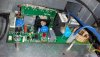
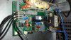
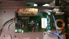
The high frequency board would allow a welder to strike an arc without touching the work piece. Mine has failed, determined through discussions and testing with an HTP tech. They are not willing to provide schematics that I can troubleshoot but are willing to sell me another board for $280 plus shipping.
I feel the problem is simple and the failed is due to age.
This board is provided 24v through an on/off switch. When connected it pulls the voltage to ground, when disconnected 24v is present in the harness. There was an audible pop during this failure, nothing looks out of place or burned. There are a few components on this board that are unfamiliar to me and I'm not sure how to test them.
I can take any picture and perform tests, I need help.
Thanks
Jason
 
The spark usually gets weak before it fails. That was the only failure mode that I had to plan for. My source for parts have been here: https://www.newark.com/search?st=spark gap It will usually flash regularly when it;s good. The electrodes either wear or oxidize and they die. A lot of times, it's discolored. That's the first component I would replace.

They have a specific breakdown voltage - high, like hundreds of volts. They can be used as part of the HV oscillator or can be used as protection.esting would require a variable high voltage power supply with current limit.
 
I have tested the spark gap device, it has continuity from the electrodes to the board. I would assume it is not the problem. When everything is connected there is no activity at the spark gap. The board is pulling down the voltage being supplied to it. Can anyone look at this tiny little board and guess what could do this? I have replaced the mosfet/transistor mounted to the heat sink, didn't fix the voltage issue.
Can someone tell me what the cardboard cylindrical device is at the top of the board? Is this an inducer? Thanks for any help.
 

Attachments

  • HF Board.jpg
    HF Board.jpg
    185.4 KB · Views: 479
  • HF Board2.jpg
    HF Board2.jpg
    167 KB · Views: 328
  • HF Board3.jpg
    HF Board3.jpg
    144.2 KB · Views: 299
Still voting for the spark gap. See if you can find any numbers. https://www.newark.com/search?st=spark gap As the gap erodes, the breakdown voltage gets higher and the circuit fails to start. There is an application circuit in the datasheet,

The spark gap should briefly light up. The voltage across the capacitor could tell you an upper limit. In other words, it has to be less than that. Measuring the voltage across the capacitor is VERY DANGEROUS. and could be FATAL. The capacitor is LIKELY the rectangular thing near the bottom of the daughter PCB. Expect something near 400-800 V so test probe insulation breakdown is a REAL ISSUE.

It would not be an issue for me since I was used to fixing 100 kV, 0.1 A and 15 kV at 1.5 A DC power supplies and 1000 W RF tube transmitters with 3000-4000 V plate voltages professionally. In high school, I built a 3000 V power supply for a science fair project and I've been working around picture tubes since I was a kid.

The cap should charge by a relativey high frequency oscillator and then break down by the spark gap. The fast pulse is applied to the primary of a transformer where the secondary is in series with the electrode. The transformer has a high turns ratio causing a very high voltage on the secondary, probably 10's of kilovolts.

The one hand in the pocket rule always applies.

I'd try to make the measurement when not actively powered and shortly after an ignition attempt with power off.
The high voltage pulse could damage your meter. One lead you can likely connect permanently if the insulation of your test probes is good enough. The second connection would be made using a long piece of PVC pipe holding the test probe.
i.e. Make a fixture, that would allow you to probe the voltage across the cap quickly after an attempted ignition and th the power off.

Normally, i'd make connections with the power off, but not in this case.

Your cardboard thing is a transformer. Since it's basically in series with the electrodes, it has a high turns ratio, but the gauge of the wires are vastly different.
 
From the comment in post #1 about the boarddragging down the 24 volt DC supply I think the fault will be in the inverter that steps the 24 volts up tp 800 or so. I think tracing out the schematic of that part of the circuit is required to diagnose the fault any further.

Les.
 
Status
Not open for further replies.

Latest threads

New Articles From Microcontroller Tips

Back
Top