Continue to Site

Welcome to our site!

Electro Tech is an online community (with over 170,000 members) who enjoy talking about and building electronic circuits, projects and gadgets. To participate you need to register. Registration is free. Click here to register now.

  • Welcome to our site! Electro Tech is an online community (with over 170,000 members) who enjoy talking about and building electronic circuits, projects and gadgets. To participate you need to register. Registration is free. Click here to register now.

High(er) Voltage Power Supply OK Circuit for microcontroller

Status
Not open for further replies.
I have a microcontroller powered by a 5V power supply. The system requires multiple other power supply voltages including 9, 12 and 24 volts. Obviously if I don't have 120VAC and 5V the microcontroller isn't going to power up. But if the 9, 12, and/or 24V supplies don't power on (or fail) the microcontroller has no way to know. I was thinking of rigging up an optocoupler and a zener diode to provide an input the power supply is online and ready.

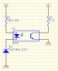
I was thinking something like this.

96342-26cbde5035c45248ee53cc20f88c523c.jpg


24V power supply, 1V Vf for the zener and the LED, leaves 22V over the 22K resistor for 10mA through the LED. The optocoupler is has a normalized CTR of 1 at 10mA. Then 1mA through the output transistor to input to the microcontroller.

It seems too easy, so I must be doing something wrong.
 

Attachments

  • PS OK v1.jpg
    PS OK v1.jpg
    86.8 KB · Views: 127
Look at Microchip and TI for voltage supervisor chips. They provide an ouput when voltage levels are too low (out of range?) for about 50 cents. They are only good for voltage ranges of 5 volts or less, but a voltage divider could easily solve this.
 
As there's no image it's impossible to know what you're on about, use the 'upload a file button' - however, if your micro has analogue inputs why not simply measure the other HT voltages?.
 
As there's no image it's impossible to know what you're on about, use the 'upload a file button' - however, if your micro has analogue inputs why not simply measure the other HT voltages?.

There is both an image inline and uploaded. I have analog inputs, but (a) don't want to spend the microcontroller cycles or memory to do the conversion and (b) it can't be done directly as the voltages are too high. So some type of voltage reduction circuitry will be required. If I use an opto isolator it will keep the high voltage away from the microcontroller in the event of a slip, oops, or component failure.
 
There is both an image inline and uploaded. I have analog inputs, but (a) don't want to spend the microcontroller cycles or memory to do the conversion and (b) it can't be done directly as the voltages are too high. So some type of voltage reduction circuitry will be required. If I use an opto isolator it will keep the high voltage away from the microcontroller in the event of a slip, oops, or component failure.

It's just two resistors to feed the analogue inputs, absolutely trivial and cheap.

I can see your uploaded image now (it wasn't there before), it seems a lot of work for a poor way of determining if a supply is there or not, and I'm dubious how well it might work.

There's little code involved in reading analogue inputs, and you probably don't need to check it that often anyway. There's also no danger with a simple resistive attenuator - personally, assuming it's a 10 bit A2D?, I'd scale the inputs to give 102.3V FSD so as to get full bit accuracy without any software scaling required. Two resistors are obviously much cheaper than 1 resistor, 1 zener, and 1 opto-coupler.
 
What makes you dubious about how well it would work? I have the same question, but am not seeing any reason it would not work.

Using a resistor divider would require a common ground between the 5V supply and the higher voltage supplies which they do not have. (ok, a point not listed in post #1).
 
The real question is whether all your power supplies are referenced to the same ground; if so, then as others have said, you don't need the isolation provided by an opto.
There are certainly lots of ways of approaching this particular problem.
 
The real question is whether all your power supplies are referenced to the same ground; if so, then as others have said, you don't need the isolation provided by an opto.
There are certainly lots of ways of approaching this particular problem.

I just beat you to the buzzer. They are not sharing a common ground. They may not even be in the same enclosure.
 
Here's another approach using Microchip MCP111 voltage detector chips. A voltage divider from each supply is scaled to provide 5 volts to the voltage detectors. The ooen drain outputs from any number of detectors can be used to provide a power good signal ir to hold the micro in reset until all the voltages are present. The vikrage detectors are about 50 cents a piece.

voltage good dect.png
 
What makes you dubious about how well it would work? I have the same question, but am not seeing any reason it would not work.

Zeners aren't perfect devices, the voltage drop and leakage will vary considerably, and your 22K resistor is far too high - as is the 22V zener, for a 24V rail. Assuming this method would work well enough, the resistor value is calculated after subtracting the zener voltage and the LED voltage (which will be more than 1V) from the rail.

Using a resistor divider would require a common ground between the 5V supply and the higher voltage supplies which they do not have. (ok, a point not listed in post #1).

That's an entirely different proposition then, so we can't really offer much advice as we've no clue what the circuit configuration is.
 
There is a microcontroller powered by one 5V power supply, other end devices (actual items irrelevant; valves, pumps, I/O, sensors, etc.) are powered by not-microcontroller-friendly voltages including 9, 12 and 24 volts. None of which share a common ground, all are controlled via relay driver and relays. The problem is to detect and verify the other power supplies are alive an well since the microcontroller cannot 'see' the status of what it is controlling (ie., even if the microcontroller has power, there is no way for it to know the end device has power; that is not 5V)

Yep. 22K is 10x too high. Seems I misplaced a decimal. But I did subtract the two 1 volt drops.

24V -2x 1V=22V; for 10mA would be a 2.2k resistor, not 22k. But still 1.4W.
 
I don't see why you need the zener at all unless it is to ensure the LED is off when the supply is below a certain level. At some point of the supply going down it's not going to get enough juice anyway. I think it's a neat solution btw.
Where do you get 1.4W from? I make it 0.22W (if you are talking about resistor dissipation)
 
The forward voltage for an optocoupler LED is closer to 2 V than 1 V. Of more concern is that it varies with temperature and from part to part. With a 1% resistor and 5% zener, the circuit still would not achieve +/-10% accuracy or repeatability. Of even more concern is that the turn on point will not be crisp. The LED will increase in brightness (and the output transistor will increase its collector current) gradually as the input voltage crosses the transition level. The exact voltage at which the output sinks enough current to be perceived as a change in state will be unpredictable.

I don't think the code to read and interpret an individual input bit is all that much less than the code to read and level-test an A/D input. But if you really want an outboard level-test circuit, I recommend using a quad opamp as four comparators (no pull up resistors needed). The LM324 was born for stuff like this.

ak
 
What happened to the zener?, the zener removes 22V from the 24V, assuming the LED drops 2V, then you have nothing left of the original 24V.

It's been a while since I have worked in-depth with zeners. As I recall, they were essentially high impedance (forgoing the break over region) until they break over then a short circuit passing all voltage through. Are you saying a 22V zener will have a 22V drop and I don't need a resistor at all?

The forward voltage for an optocoupler LED is closer to 2 V than 1 V. Of more concern is that it varies with temperature and from part to part. With a 1% resistor and 5% zener, the circuit still would not achieve +/-10% accuracy or repeatability. Of even more concern is that the turn on point will not be crisp. The LED will increase in brightness (and the output transistor will increase its collector current) gradually as the input voltage crosses the transition level. The exact voltage at which the output sinks enough current to be perceived as a change in state will be unpredictable.

I'm not worried about an exact break over or measuring the voltage, just on-off yes or no. The datasheet for the 4N35 is closer far closer to 1V than to 2V, as I read it.

The power supply will either be on or off. I'm not worried about a brown-out situation (ie. 24V PS that is only outputing 23.8V.

I don't think the code to read and interpret an individual input bit is all that much less than the code to read and level-test an A/D input.

The difference is one of code versus one screen of code, including the setup and configuration of the pins.

But if you really want an outboard level-test circuit, I recommend using a quad opamp as four comparators (no pull up resistors needed). The LM324 was born for stuff like this.
How do you maintain isolation with the LM324? I'm not seeing it.

I don't see why you need the zener at all unless it is to ensure the LED is off when the supply is below a certain level. At some point of the supply going down it's not going to get enough juice anyway.
I wanted to make a sharper threshold for the LED power, than provided by a resistor or resistor divider (which are basically linear).

I think it's a neat solution btw.
Thank you.

Where do you get 1/4W from? I make it 0.22W (if you are talking about resistor dissipation)
No such thing as 0.22W resistor, so 0.25W and includes some fudge factor.
 
Do you really need an accurate voltage measure or just an indication that the voltage is available, assuming that if it's available it's the correct value (which would normally be the case)?
 
...if the 9, 12, and/or 24V supplies don't power on (or fail) the microcontroller has no way to know. I was thinking of rigging up an optocoupler and a zener diode to provide an input the power supply is online and ready.
Just roll call. Are you awake or dead?

Bueller? Bueller?
 
No such thing as 0.22W resistor, so 0.25W and includes some fudge factor.

You put 1.4W in post #11, as in 1 watt and another 4 tenths of a watt! Yes, 1/4 W makes much more sense :)
 
The MCP111 voltage monitor will sink 10mA to drive an opto-isolator, give a reliable, stable turn-on voltage and draw virtually no current.

Just sayin.....
 
Status
Not open for further replies.

Latest threads

New Articles From Microcontroller Tips

Back
Top