Continue to Site

Welcome to our site!

Electro Tech is an online community (with over 170,000 members) who enjoy talking about and building electronic circuits, projects and gadgets. To participate you need to register. Registration is free. Click here to register now.

  • Welcome to our site! Electro Tech is an online community (with over 170,000 members) who enjoy talking about and building electronic circuits, projects and gadgets. To participate you need to register. Registration is free. Click here to register now.

high current power supply circuit.

Status
Not open for further replies.

Bondfire

New Member
Hi pple.

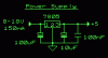
The power supply circuit shown below outputs 5V with 100mA current.

How can i modify it to give a higher output current? I need to
power about 20 circuits (IR, force sensors,limit switches) so i need
a higher output current....i'm not sure exactly how much current these circuits will draw coz info is not given on the datasheets...but can some1 tell me in general how to increase the output current?

Thx a lot!
Bondfire
 

Attachments

  • psu_5v.gif
    psu_5v.gif
    930 bytes · Views: 1,891
Actually a 7805 will put out 1 Amp.
The only reason it doesn't in that circuit is because to input current is also low. It say 100 to 150ma in.

But the Real Question is: How Many Amps do you need?
 
Bondfire said:
Hi,

Lets say i need 5A....wot should i do?

You can get a larger version of the 7805, 5A in a TO3 case. You should be aware though that analogue regulators like this will require large heatsinks! - as will the 1A version, if using high currents and high input voltages.

You really need to find out what your requirements are, pointless spending money you might not need to.
 
Nigel Goodwin said:
Bondfire said:
Hi,

Lets say i need 5A....wot should i do?

You can get a larger version of the 7805, 5A in a TO3 case. You should be aware though that analogue regulators like this will require large heatsinks! - as will the 1A version, if using high currents and high input voltages.

You really need to find out what your requirements are, pointless spending money you might not need to.

Or if a TO3 package doesnt appeal to you, you can use an outboard power transistor to "boost" the current. In essence it will share the load with the '7805 as well as the dissipation and it's cheap!
You can google for boosted linear regulator or similar, I'm sure you'll find a reference design.
 
The circuit of high current linear regulator using bypass transistor is also given in 78xx datasheet. Check the datasheet for schematic.
 
I don't know your requirements, but if you're not after something portable or battery operated and don't mind bulky size/weight then might i suggest an atx power supply?

The 5 volt line on an ATX computer power supply can give ya 30-50 amps (depending on the model) and its already regulated.

If you want it silent, and you don't plan on pulling more than 10 amps you can just disconnect the fan.

There are plenty of guides on the internet on how to start up an ATX and get it working for you.

Like i said i don't know your requirements, sorry if this isn't what you wanted.
 
another option is to add transistor, inductor and shottky diode and
make it work as switching regulator. Keeps efficiency higher than
analog regulator would have and reduces heat while provides higher
output current than source can provide.
but did you consider any other PSU like one from old PC (if this is just a
bench top psu)?
 
Here is a hand drawing of my regulated PS, and it can be modded to run heavier loads, please note I drew the cap is upside down but showed correct polarity. I also wrote the turn ration backwards, hey I drew this at 3am. Well I guess the turns ratio is right NM on that.

Since resolution is limited the + sign turned into a - sign on pin 7.
 

Attachments

  • scansm.jpg
    scansm.jpg
    77.1 KB · Views: 1,299
Hi Juglenaut,
About your power supply:
1) What is the purpose of your pot? To blow-up the pot and the zener diode?
2) Doesn't the circuit produce a lot of ripple, since the zener diode is referenced to the positive of the supply instead of to ground?
3) What mod do you suggest to it for it to drive a heavier load with more than only 50mA?
 
Actually oh skeptical one this circuit got top grade in the class.

99.8% regulation 0.4% ripple with 4kuf with 1k bleed, 64.5 mA total current DC.

The pot is to set the 5.1 volt typical zener at 5 volts exactly for reference to a high Zin op-amp. Only a few mA goes through the zener and the 50k pot.

The basic idea is in the book "The Art of Electronics" Cambridge University.

Seeing how the load is mostly over the transistor and the bridge rectifier. I think increasing to a higher spec component would do the job. The op-amp I used can take 24 volts +- at pin 7 and negative 24 at pin 4. I am able to run a 4 ohm load with no over heating into distruction as is.

Please note that the pot is acting like a 50k resistor to ground from a 12 volt source in which I didn't draw in a first drawing, as it was a step towards a final stage. I am so sorry I have nothing better to do than to post all day I would have caught it but I need to work to make money and time is limited.

Why referance the zener to ground directly, wouldn;t it be the same by referencing to positive?? It doesn't need to be, if the electric simularity is referanced to ground through a resistor. In effect you are wrong by saying it is not referanced to ground when in actuality it is very well referanced to ground and positive though a set amount of resistance.
 
Juglenaut said:
Actually oh skeptical one this circuit got top grade in the class.

Sorry, but I agree with Audioguru, if your circuit is as the drawing shows?, it's a really crap design, and wouldn't work well. If you've made a mistake in the drawing?, fair enough - but as shown it's not a practical usable circuit.

BTW, what year are you in?, I'm presuming school rather than Uni?, and electronics teachers in schools mostly know next to nothing (or less than nothing?) about electronics!.
 
Juglenaut said:
The basic idea is in the book "The Art of Electronics" Cambridge University.

The Art of Electronics has examples of "Bad Circuits", are you sure you did not copy it from one of these?

JimB
 
Hi Juglenaut,
You can learn things only if you understand them, so I'll explain a few things. Then you can teach your teacher like I did.
I'll point out problems with your power supply schematic and sketch an improved one later. First let's select a zener diode:

1) The 1N4733 zener diode that you used has a minimum voltage of less than 5V, so is not suitable for use in your circuit that doesn't have gain.
2) The 1N47xx family of zener diodes are tested and rated with an operating current of a whopping 49mA!
3) The 1n4735A 6.2V zener diode would have been a better choice because:
a) Its minimum voltage of 5.89V exceeds your 5.0V requirement and can easily be reduced with a pot across it.
b) Its maximum zener impedance is less than 1/3 that of the 1N4733 (the lower it is, the better the voltage regulation at its operating current).
c) Not shown on the datasheet is the voltage change with temperature change of the 1N47xx family. The 6.2V zener diode changes its voltage with temperature change less than the 5.1V one.

4) I would have used a BZX79C6V2 zener diode because it has a minimum voltage that exceeds your requirement.
5) The BZX79Cxxx family of zener diodes are tested and rated with an operating current of only 5mA.
6) It has a very low zener impedance at its operating current.
7) It has a low voltage change with temperature change.
 

Attachments

  • zener_diodes.gif
    zener_diodes.gif
    60.6 KB · Views: 461
An easy improvement to the design would be to pulse width modulate the input in a simple buck topology.
Use the uc3842 bipolar chip (cheap), and surround it with the necessary parts. I'm sure you can find an app note at TI regarding this application.

Your regulation will be close to perfect, good loop response, current limited
high frequency, very efficient , easy and above all cheap.

:wink:

Ldi Edt
 
The best way is to used the data sheet of 7805. There are many examples in how to increase the current in data book.
 
Status
Not open for further replies.

New Articles From Microcontroller Tips

Back
Top