Continue to Site

Welcome to our site!

Electro Tech is an online community (with over 170,000 members) who enjoy talking about and building electronic circuits, projects and gadgets. To participate you need to register. Registration is free. Click here to register now.

  • Welcome to our site! Electro Tech is an online community (with over 170,000 members) who enjoy talking about and building electronic circuits, projects and gadgets. To participate you need to register. Registration is free. Click here to register now.

High current low voltage linear voltage regulator

Status
Not open for further replies.
Ive been looking for a 3v to 13v 150a circuit that can supply a load that's ~60mohm for some testing purposes.
This circuit (with more transistors or higher amp capible ones) jumps out to me as being suitable and suitably easy to put together.

100ampvariablepowersupplycircuit_zpsadfedghg.png


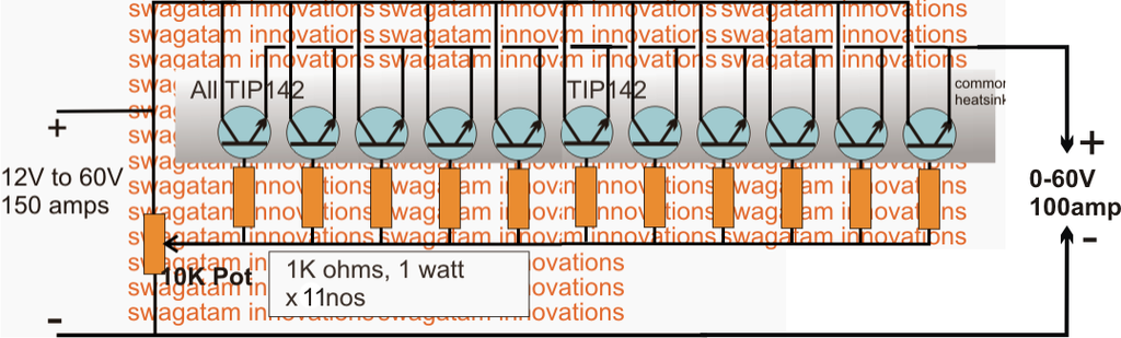
Couple of questions here; the Vin on the schematic is too high, will it work with lower voltage?, is the base current/voltage too high to use a surface mount momentary switch trigger after the pot?, and will it function properly with such a low resistance load?

Im hoping it'll work, but if your answers are no, yes, no.. could you point me in the direction of a better circuit please :angelic:

I've got a sizable heatsink with a micro fan to mount it to, though the circuit can't be more than 5mm proud of it.

As always, any help is greatly appreciated.
 
from where i see it the circuit has a a mis-configuration
  • It is true that 100A is a lot of current to put anything to the current path
  • It is also true that - as it is the emitter follower config. - the load would cause the emitter feedback
    -- the emitter feedback is to compensate the neg. temp coefficient of the semiconductor materials
  • neg.FB.1 -- probably the correct solution would be tie bases together and equalize bjt switches with small emitter resistors
    -- otherwise the they would strobe (conduct at undefined states) as multiple diff-amp shoulders
  • neg.FB.2 -- also helpful could be setting all bases to individual voltage divider biasing as something instead of 1k to base and something from base FW to emitter
    -- i'd consider using a different supply to enable max turn on @ high output currents and/or low input voltages . . .
    -- (note! -- that this conflicts with "neg.FB.1" . . . but it can be config.-d to merge/suit)
  • there might be more . . .
btw. spotted somewhat related read (at quick scan for web tutor.-s) **broken link removed**
is about ~test (a lot of precision and safety elements required to drive FET-s within ±1V ΔVg and SOA :meh:)
HCRS-test_0E00-0000.png
 
Last edited:
13V will drive ~216A through a 60mΩ load! The circuit shown isn't designed to handle that.
Rather than a bunch of modest power BJTs as shown, have you considered using a big IGBT or a few MOSFETs?
Are you looking for a constant current source, one that limits the output to 150A, or just one that can cope with 150A maximum?
How long must the load current be maintained?
 
Ci139. Tbh most of that went straight over my head :confused: the bit I do understand is; its a bad circuit so I'll keep looking. Thanks.
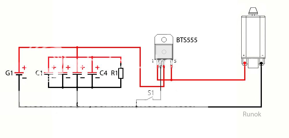
Alec_t. With the tests I want to carry out, the higher voltages I'll be using will be on a much higher ohm load, it's just the low voltage that needs the high amps. 150a as a maximum should be plenty but I guess a fool proof circuit that can handle the highest output, (just incase I leave it turned up to 13v by mistake) would make sence. Yes I can use mosfet, and given what Ci139 has said it seems I'll not be using the original schematic anyway. In operation it'll be live for only a few seconds at a time.

Any suggestions on a most basic (on par with the one in my first post) ~5mm deep, high current linear vv circuit would be awsome at this point, Google's suggestions are either not capible enough or too big.
 
Last edited:
I don't see how you'll safely squash it all into a 5mm gap. You'll be dissipating around 1kW, albeit perhaps briefly, so will a micro fan cope?
Are you wedded to the linear approach? A SMPS would be a lot more efficient.
 
The smps is a much better approach, but it's costly and I can't put one together myself. If I could, I would!
I'll have one made to suit my needs eventually, but until then I need to know what my needs are exactly. Hence testing the various loads I have in mind.

I'll be machining the heatsink, I could go with glycol cooling as well as the fan.. assuming I can find a small enough pump. Though honestly, if it gets 'manageably' hot I don't mind so much, successful testing is the important bit.

I'm making a pocket power source with interchangeable tools, having the prototype a similar size the the finished article is important, the 5mm gap could be enlarged I guess but I'd much rather not. The ergonomics is a concern as I'm not only making the power source but also making the tool attachments myself. Not all my ideas will pan out, getting a SMPS now means all the testing will be done with it and blowing it up is a strong possibility, the cheap and easy linear control makes sence for now.

If you know of 200+a smps, small and cheap or easy to make I'm all ears! :)
 
Last edited:
this editor sucks -- it cant be used for working -- another entertainment site . . .

((nothing to do ... maybe there's something to adapt from ...))


Блок питания на микросхеме LM723, 12 вольт 25 ампер

http://www.diagram.com.ua/list/power/power487.shtml

http://www.diagram.com.ua/list/power/487.ht4.gif


http://www.110volt.ru/sovety/power-supp_12v_24v

Блок питания 12в 30а

view-source:http://www.110volt.ru/sites/foto/sovety/samodelki/12v30a.gif

Схема блока питания мощностью 20 Ватт с защитой

view-source:http://www.110volt.ru/sites/foto/sovety/Power_Supply/20w_pa.jpg


http://kamrc.ru/index.php?topic=105.15


(you only need one shoulder of it . . . in priciple)

http://hobbyelectronicsdri.blogspot.com/2011/04/1000w-mosfet-legend-stage-master-mk2.html

http://2.bp.blogspot.com/-g-ZN6QLJ8XE/TZp6D9hzcqI/AAAAAAAAAMc/E1JlH8gUlUg/s320/NChannel.gif


(▼ the web search "hooked up" at 60 amperes // it's counting down from 500A // ??? ▼)

http://electronics-diy.com/power-supply-lm317-2n3055-0-28v-6-8a.php

http://e-belajarelektronika.com/membuat-power-supply-12-volt-35-ampere/

http://abisabrina.wordpress.com/2014/04/19/skema-regulator-dc-12volt-35ampere-sederhana/

http://skema-rangkaian-elektronika.blogspot.com/2009/08/rangkaian-regulator-power-supply-20a.html


(more)
http://coefs.uncc.edu/dlsharer/files/2012/04/F6.pdf
(if i'd DELETE-d this to one line the links would be automatically merged by this dummy "editor" . . . !it's a miracle! (only the one not required here idiots) ) , http://www.reuk.co.uk/wordpress/electric-circuit/high-current-voltage-regulation/

( by : ) http://www.google.com/search?q="power+transistors"+regulating


Last edited:
Scrolling through circuits I found this one..
15791589_zps63vgpoo8.jpg

I've no idea what the caps and resistor are for in that topology, but it made me wonder.. could an RC setup like that smooth out a pwm control so the load gets a fairly steady average voltage?
This would be pretty easy to make and the bts555 could handle the amperage I'm looking for. Pwm doesn't suit my plans but if I could smooth the pulses to an average it might be worth an trial :)
 
What you're suggesting is similar to what is done in a SMPS. The pulses are smoothed (averaged) by a series inductor and shunt capacitor. This is less lossy than using a resistor/capacitor filter.
 
What is the duty cycle of the loading? It matters a lot when it comes to selecting transistors and heatsinks.
 
While there is nothing blatantly wrong with the schematic in post #1, it does have room for improvement.

1. There is no reference voltage and feedback, so this is a crude "regulator" whose output will increase as it warms up. Depending on the transistors, that increase could exceed 0.25 V.

2. The design lends itself to thermal runaway. As a BJT (bipolar junction transistor) heats up, its base-emitter junction forward voltage decreases. Even with individual base resistors, the transistors with the lowest Vbe when cold will conduct the most current, heat up first, and conduct more current as they starve the cooler transistors with higher Vbe's. The solution is a small power resistor in series with each emitter. The larger the resistor value, the more power is wasted. BUT, the less the individual Vbe's matter and the better the current sharing among the output devices.

3. There is going to be amps of base current trying to go through the pot. Power darlington's make the thermal management issues worse, but reduce the base current by 50:1.

4. Power MOSFETs do not have the thermal runaway problem, and naturally current share better than BJTs. But the transconductance is much more temperature sensitive, and in a follower arrangement there will be a much larger voltage between the gate and source than between a base and emitter.

5. Rethink your fan size. With a 4 V input, 3 V output, and 150 A, the transistor array will develop 150 W in component heat. If the parts are all in a row on a heatsink, the ones away from the fan are going to be "cooled" with very hot air, so the air flow has to be increased to cover that. There are many fan calculators on the web. Here is the equation for the best-case, perfect condition where 100% of the air touches 100% of the hot component surfaces. You derate from there.
https://www.nmbtc.com/fans/engineering/airflow-formula/

ak
 
looking at the schematic in post #1, it uses 11 TIP142 in parallel.

TIP142 datasheet:

https://www.onsemi.com/pub/Collateral/TIP140-D.PDF

OK, NPN power darlington, 10A max continuous current.

Looking at the TIP142 On-characteristics (page 2)

DC current gain: 500 minimum (for 10A and Vce 4.0 volts)

Base-Emitter on voltage: 3.0 V (for 10A and Vce 4.0 volts)

So at best 11 in parallel would handle 110A and drop at least 4.0 volts.

They would require a base supply current of 10A/500 -> 20 mA each
so 220 mA for 11 TIP142s.

Also each 1K base resistor would drop 20mA * 1K -> 20 volts so the
feed to the 1K base resistors would need to be

<1K resistor drop>+<base-emitter-on+voltage>+<output voltage>

20 V + 3 + output voltage

This is not counting the thermal stability problem. A TIP142 which
has a lower Vbe than the others will hog more of the current running
hotter causing it to hog more until it dies. Then the next lowe Vbe
hogs the current...
 
This is not counting the thermal stability problem. A TIP142 which
has a lower Vbe than the others will hog more of the current running
hotter causing it to hog more until it dies. Then the next lowe Vbe
hogs the current...

Not a problem, as you fit emitter resistors in series with each emitter, this ensures current sharing.

No one (with any sense) would parallel transistors without them, it's a VERY basic and obvious part of the circuit.

The original circuit as posted wasn't really even a 'circuit' at all, it's non-functional on pretty well every level.
 
The links in post #1 and #9 are broken. Upload the images here using the 'Upload a File' button.
 
The post #9 link is still broken. All I see is an image requesting the OP to update his pohotobucket account.
 
Photobucket have just updated their terms of service.. now I can't share images, like I have for the past 6 years or so :mad: . They won't allow access to any of my pics, even for my own personal viewing, unless I pay £200 or so. Guess they've got their reasons but to me it's a lot like being held to ransom.
 
Ouch! I've never liked the idea of entrusting any files to 'the cloud'.
 
Status
Not open for further replies.

Latest threads

New Articles From Microcontroller Tips

Back
Top