Continue to Site

Welcome to our site!

Electro Tech is an online community (with over 170,000 members) who enjoy talking about and building electronic circuits, projects and gadgets. To participate you need to register. Registration is free. Click here to register now.

  • Welcome to our site! Electro Tech is an online community (with over 170,000 members) who enjoy talking about and building electronic circuits, projects and gadgets. To participate you need to register. Registration is free. Click here to register now.

hFE vs. Beta

Status
Not open for further replies.

DigiTan

New Member
For bipolar transistors, is there any difference between the "β" figure and "hFE?" And what exactly does hfe stand for?
 
Beta is hFE which is a transistor's DC current gain at a particular temperature, current and voltage.
Hfe is a transistor's AC current gain which is less and decreases with increasing frequency.
 
Okay, I guess those engineering types really liked their greek letters. :lol:

I want to be 100% sure I understand exactly what 'saturation' means. The way I gather, a NPN transistor is saturated with it's base voltage is greater than its collector voltage (typically by 0.4V?). Otherwise, it's in the "active" mode. And a NPN with its base grounded is in the "cutoff" mode.

Is all this looking on-target so far?
 
DigiTan said:
Okay, I guess those engineering types really liked their greek letters. :lol:

I want to be 100% sure I understand exactly what 'saturation' means. The way I gather, a NPN transistor is saturated with it's base voltage is greater than its collector voltage (typically by 0.4V?). Otherwise, it's in the "active" mode. And a NPN with its base grounded is in the "cutoff" mode.

Is all this looking on-target so far?

I'm probably wrong here, but isn't saturation simply when the transistor is turned all the way on? .7-.8 volts on the base relative to ground. Otherwise the base voltage might be 6.4 volts for example, which would probably wreck the transistor.
 
DigiTan said:
I want to be 100% sure I understand exactly what 'saturation' means. The way I gather, a NPN transistor is saturated with it's base voltage is greater than its collector voltage (typically by 0.4V?).
You cannot cram any more current into a transistor's base-emitter junction when the collector voltage is so low that there is forward-biased base to collector current! That's when most transistors are saturated at low collector current.

A 2N3055 transitor just runs out of current gain when it saturates at high current. Its base-emitter voltage can be as high as 1.5V and collector voltage as high as 1.1V with a collector current of only 4A and a base current of 400mA. With a collector current of 10A and a base current of 3.3A, its collector saturation voltage could be as high as 3V.
 
What I learnt at school was that a transistor is said to be saturated when any increase in base current does not result in appreciable increase in collector current and Vce remains almost constant.

Have I got this concept wrong?

audioguru said:
You cannot cram any more current into a transistor's base-emitter junction when the collector voltage is so low that there is forward-biased base to collector current! That's when most transistors are saturated at low collector current.

:oops: :oops: Sorry to ask such a question...
I am assuming that the circuit is a CE configuration. And the collector resistor is much larger than the emitter resistor. So the collector voltage is low.

The potential divider at the base has made the Base-Collector Junction forward biased and the base emitter junction forward biased as well? :oops: :oops: :oops:

I can sense that something I am writing sounds foolish... Please enlighten me.
 
Yeah, this one was in the CE configuration.

So for low-distortion gain, I would need to bias the transistor into the active mode, right?

Does the opposite case apply to MOSFETs? In our examples, we always had the MOSFET in saturation mode because the triode mode had an exponential I-V characteristic that distorted the signal--whereas saturation was mostly linear. Is this part correct?
 
DigiTan said:
So for low-distortion gain, I would need to bias the transistor into the active mode, right?
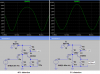
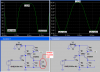
For low distortion in a transistor common emitter transitor circuit, keep the output voltage well away from the supply voltage and use plenty of negative feedback by using an unbypassed emitter resistor or other ways. I attach a sim of a transitor producing about 40 percent distortion!
With the emitter resistor unbypassed, the distortion is only (!) 3%. The distortion is lower at lower levels.

Does the opposite case apply to MOSFETs? In our examples, we always had the MOSFET in saturation mode because the triode mode had an exponential I-V characteristic that distorted the signal--whereas saturation was mostly linear. Is this part correct?
I have seen Mosfets and Jfets as linear resistors in the saturation mode where there isn't a DC supply and the signal across them is 100mV or less. Usually they are used in their active triode mode with plenty of negative feedback to reduce distortion. :lol:
 

Attachments

  • sim_transistor_distortion.png
    sim_transistor_distortion.png
    34.6 KB · Views: 804
Alright. Also we were studying CE amplifiers with and without the emitter resistor, and it was pointed out that it is usually best to include the resistor but I didn't understand why. What is it about Re that improves performance, and what;s the role of the capacitor that you sometimes see across it?
 
Hi Digitan,
Look at my sim example.
With the emitter resistor bypassed on the left, the gain is 18 times or more than the other, but it has 40% distortion at high levels.
The one on the right side is the same except I changed a bias resistor so it is better centered and it doesn't have a bypass capacitor across its emitter resistor. The emitter resistor then provides negative feedback which reduces the gain 18 times or more and reduces the distortion down to 3%. :lol:
 
Okay, so bypassing the Re causes the gain to be increased, but causes distortion because the transistor was driven into saturation. And when the resistor can't be bypassed, the gain stays low. Is this part correct?
 
DigiTan said:
Okay, so bypassing the Re causes the gain to be increased, but causes distortion because the transistor was driven into saturation. And when the resistor can't be bypassed, the gain stays low. Is this part correct?
The gain is slightly lowered, and it depends on resistance. Distortion and gain tend to inverse each other.

isn't saturation simply when the transistor is turned all the way on?
To me, yes. saturating the transistor is like flooding a car :lol:
 
DigiTan said:
Okay, so bypassing the Re causes the gain to be increased, but causes distortion because the transistor was driven into saturation.
No. It isn't saturated and it isn't cutoff. It is just very badly distorted because transistor circuits as simple as this are lousy.

And when the resistor can't be bypassed, the gain stays low. Is this part correct?
Correct. But I increased the input level about 18 times so that both have the same output level.

Here are both circuits with the input levels increased so that the transistor is saturated and is cutoff:
 

Attachments

  • sim_transistor_distortion2.png
    sim_transistor_distortion2.png
    38.3 KB · Views: 687
mstechca said:
The gain is slightly lowered, and it depends on resistance.
No. Bypassing the emitter resistor increases the gain 18 times or more. Since the resistor is bypassed with a 100uF capacitor that is like a dead short to the signal at the emitter, then the transistor doesn't have any negative feedback. Negative feedback reduces gain and distortion and increases bandwidth.

Distortion and gain tend to inverse each other.
No they aren't, look at my pics. The one with high gain also has very high distortion. Negative feedback reduces gain and distortion.
 
Ah, okay. It looks like I've been making a nasty habbit on paper of confusing saturation with cutoff. I've gotta remember 'saturation' is high current, low Vcollector; and not high current, high Vcollector.

Also, I've been wondering: why is the CE amp typicaly seen in the inverting configuration and not the voltage-following mode? Is it because of performance or is it just the convention?
 
DigiTan said:
why is the CE amp typicaly seen in the inverting configuration and not the voltage-following mode? Is it because of performance or is it just the convention?
A voltage-follower doesn't have any voltage gain.
It has a very high input impedance but its output is easily overloaded.
 
audioguru said:
mstechca said:
The gain is slightly lowered, and it depends on resistance.
No. Bypassing the emitter resistor increases the gain 18 times or more. Since the resistor is bypassed with a 100uF capacitor that is like a dead short to the signal at the emitter, then the transistor doesn't have any negative feedback. Negative feedback reduces gain and distortion and increases bandwidth.
I was making an assumption that no bypass capacitor was used.

Distortion and gain tend to inverse each other.
No they aren't, look at my pics. The one with high gain also has very high distortion. Negative feedback reduces gain and distortion.
I forgot to add gain.

for some odd reason, this week must be my make accidental mistakes week. :oops:
 
Status
Not open for further replies.

Latest threads

New Articles From Microcontroller Tips

Back
Top