Continue to Site

Welcome to our site!

Electro Tech is an online community (with over 170,000 members) who enjoy talking about and building electronic circuits, projects and gadgets. To participate you need to register. Registration is free. Click here to register now.

  • Welcome to our site! Electro Tech is an online community (with over 170,000 members) who enjoy talking about and building electronic circuits, projects and gadgets. To participate you need to register. Registration is free. Click here to register now.

Help with zetex h-bridge

Status
Not open for further replies.

dirtyb15

Member
Alright, i am getting upset. I dont have very much documentation for the h-bridge i am using, but it is part no. zhb6790.
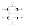
Anyways, i am using 2 pins from a pic to drive a coil/magnet, type device. I have have 1 pin of the pic tied to the bases of the upper left, and the lower right (using current limiting resistors). The pin 2 from the pic to the other bases. When i first powered it up at a freq of 40Hz it seemed to be working fine. I had the voltage pretty low, about 3 volts, and the coil was drawing about a quarter amp. However, when i took it past 5 volts it drew about 1 amp and blew out the chip. It says on my data sheet they are rated to 2.5 amps. What am I doing wrong here? Does anyone have any diagrams on wiring up one of these chips?
thanks for any help.
Dave
 
A picture paints a thousand words...
IF you look at the chip layout it has NPN for the lower devices and PNP for the upper devices. Thus you do not need to cross-wire your base-drive signals

ie:
Signal1 => B1 & B3
Signal2 => B2 & B4

IF you wire
Signal1 => B1 & B2
Signal2 => B3 & B4

Then if Sig1 is HIGH and Sig2 is LOW then current will flow from C3->C1 (assuming load connected).
IF Sig1 is LOW and Sig2 is HIGH then current will flow the other way


https://www.electro-tech-online.com/custompdfs/2005/10/ZHB6790.pdf
 

Attachments

  • zetex.png
    zetex.png
    13.1 KB · Views: 656
Thanks

Ahh, now the picture does help. I cannot get onto their website for some reason. Am i correct in assuming these chips will be able to handle a constand 1.5 amp draw at around 12 Volts? Seems like a lot for a little surface mount??
 
It would not be able to handly 12V @ 1.5A it would def blow.

But dont underestimate Zetex, they are one of the best chip makers and I dont think I have a single design that needs some low amps (1A) driving that does not use Zetex's chips

They state a max Collector current of 2A so that will probably be when the BJT is in saturation, which if you are using it ias a H-Bridge you probably are.

What I think happened is you did not saturate the BJT's enough when they blew and thus rather then being Fully-on they were operating in their linear region and were dissipating alot of power and basically the chip cooked itself to death

Can you post yr circuit (with all you rpower rails as well)
 
Schematic

here is what i just tried. Can i use the 1k and tie the bases of the npn and pnp like this? What all have i messed up :oops:
thanks,
 

Attachments

  • hbridge.doc
    70 KB · Views: 210
Urrr dirty Microsoft propietory file formats.

You do know you can attach piccies to this forum, also download GIMP ( www.gimp.org) and install the windows version to shrink the piccy.


As to the cct, yes the 1k to both base's is fine as long as the voltage sourcing them is at least 6V (or equal to the H-bridge rail) otherwise the PNP will not be fully off and they will sit in their active region and a potential shoot-thorugh will occur

This is what I think happened in the 1st place
 
Sorry about the file, I cant install many things on my work computer.
You are right though, i am only putting about 4.5V to the base. Thanks for the help!!
 
dirtyb15 said:
Sorry about the file, I cant install many things on my work computer.
You are right though, i am only putting about 4.5V to the base. Thanks for the help!!

dont worry abt the fileformat, its just I was in Linux at the time and it is a pain to startup OpenOffice.

but yer if you are only feeding 4.5V to the base and the main power-rail is at 6V you going to not be saturating all yr Chips

Try getting some NPN transistors and use the PIC to drive the base of the new transistor. Have a pullup resistor to the 6V and the collector connection of this transistor can then feed the base of the H-bridge.

That way you will be able to provide enough voltage to the H-brige to saturate it enough
 
Styx said:
Urrr dirty Microsoft propietory file formats.

As to the cct, yes the 1k to both base's is fine as long as the voltage sourcing them is at least 6V (or equal to the H-bridge rail) otherwise the PNP will not be fully off and they will sit in their active region and a potential shoot-thorugh will occur

This is what I think happened in the 1st place
The way it is connected, there is a direct current path through the bases on each side - a sure recipe for smoke. You need a resistor for each base. I'm not an H-bridge expert, but it seems to me you should probably also drive each resistor from a separate driver (4 pins in all) to allow the possibility of some dead time. This will allow the ON transistors to come out saturation (storage time) before the opposite pair comes on. Is this not a problem at 40Hz?
 
Ron H said:
Styx said:
Urrr dirty Microsoft propietory file formats.

As to the cct, yes the 1k to both base's is fine as long as the voltage sourcing them is at least 6V (or equal to the H-bridge rail) otherwise the PNP will not be fully off and they will sit in their active region and a potential shoot-thorugh will occur

This is what I think happened in the 1st place
The way it is connected, there is a direct current path through the bases on each side - a sure recipe for smoke. You need a resistor for each base. I'm not an H-bridge expert, but it seems to me you should probably also drive each resistor from a separate driver (4 pins in all) to allow the possibility of some dead time. This will allow the ON transistors to come out saturation (storage time) before the opposite pair comes on. Is this not a problem at 40Hz?

yes a soft shoot-through is a possibility in this arrangement and true prolly best to drive each tranny with its own signal. There are ways in hardware to make the deadtime if pins are short.
 
If you can't get on zetex's website, a quick google search with the "part number" and "datasheet" will turn up it's datasheet.
 
I have enough extra pic outputs, so I'll use one for each. Ill let you guys know how it goes. Thanks for the help!!
 
Status
Not open for further replies.

Latest threads

New Articles From Microcontroller Tips

Back
Top