Continue to Site

Welcome to our site!

Electro Tech is an online community (with over 170,000 members) who enjoy talking about and building electronic circuits, projects and gadgets. To participate you need to register. Registration is free. Click here to register now.

  • Welcome to our site! Electro Tech is an online community (with over 170,000 members) who enjoy talking about and building electronic circuits, projects and gadgets. To participate you need to register. Registration is free. Click here to register now.

Help with transistors

Status
Not open for further replies.
is there a different method that can give a gain? because at the level of the ttl signal the led was not bright enough since the typical forward voltage of the led is 3.8V and the ttl is only 3V

thanks
 
Last edited:
is there a different method that can give a gain? because at the level of the ttl signal the led was not bright enough

thanks
You're going to have to use two transistors. What supply voltages do you have available?
 
This should work, but it won't handle a 100ns pulse.
 

Attachments

  • LED driver.PNG
    LED driver.PNG
    10.1 KB · Views: 137
is there a different method that can give a gain? because at the level of the ttl signal the led was not bright enough since the typical forward voltage of the led is 3.8V and the ttl is only 3V

thanks

your problem here is the source current available from the TTL output. the transistor should provide the required current gain.
 
your problem here is the source current available from the TTL output. the transistor should provide the required current gain.
He says the TTL signal is 3V, and the LED fwd voltage is 3.8V. An emitter follower won't work.
 
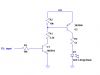
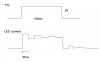
Hi, sorry to bring this up again. The circuit finally worked, it managed to send an amplified square pulse to the LED. I did it using the original design with the 2N2369A transistor. But now the pulse has this strange teeth-like shape as shown in the picture. Is it due to the transistor or the reflections of the BNC cable or something else? I'm wondering if there is a way to fix this.
 

Attachments

  • LED_current.jpg
    LED_current.jpg
    13.9 KB · Views: 132
Last edited:
Those are classical transmission line reflections due to the load and/or source impedance not matching the Z0 of the line (coax).
 
Last edited:
Status
Not open for further replies.

Latest threads

New Articles From Microcontroller Tips

Back
Top