Continue to Site

Welcome to our site!

Electro Tech is an online community (with over 170,000 members) who enjoy talking about and building electronic circuits, projects and gadgets. To participate you need to register. Registration is free. Click here to register now.

  • Welcome to our site! Electro Tech is an online community (with over 170,000 members) who enjoy talking about and building electronic circuits, projects and gadgets. To participate you need to register. Registration is free. Click here to register now.

help with transistors as switches

Status
Not open for further replies.

frubo

New Member
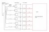
Hi there. I'm designing a circuit so that I can control 6 switches of a device using transistors and the serial port on my computer. I have 6 data pins going into the base of 6 transistors. The positive end and negative end of each switch is going to each collector and each emitter is going to ground of the serial port. Basically, when the data pin is on the transistor draws current from the device to the ground of the serial port and the switch is off. When the data pin is off the transistor has high impedence so the current goes through the switch instead and it is on.

I have found that this works for just one switch but not when I hook up the others. I have a theory that too much current is being drawn from the device to the ground of my serial port for one switch and not allowing for enough current at the other switches. i tried placing different resistors at the collector of the transistors but i am unsure what values to use and the ones i tried still dont work.

If it helps I know that there are about 3 micro amps going through each switch when it is on. I need to keep the current around this value without adding or drawing too much. I have also heard of relays which would work but I would rather not go that route. Any ideas on what I should do or how I should change my circuit? thanks.
 
Is there a resistor between the port pin and the base of each transistor?
 
yeah. Here is what I have right now. Not sure about the 10k resistors but they limit some of the current being drawn so I thought I would put them there.
 

Attachments

  • my_schematic.JPG
    my_schematic.JPG
    45.7 KB · Views: 179
also the negative side of the switches goes directly through the transistor to ground and so I think it maybe be drawing current up there too. I thought about using a diode so current cant flow up the negative side but I dont have one to use with such a small current.
 
What software are you using on the PC?? Serial ports are 12 volts low, -12 volts high. I'm confused.
 
Last edited:
Are you sure that you are not using the "Parallel Printer Port"?

Also, if you are trying to do the same thing as closing the switch would do by shunting the switch with a NPN transistor, it will work only if the following conditions are met:

Of the two red wires in your diagram on any given channel, one must be grounded inside the box to the right; and the other must have a positive voltage on it while the switch is open. The ground side of all six switches must be tied to together and grounded in the box. The six emitters of your transistors must be tied to the box ground and to the computer ground. If you cannot tolerate a common ground between the computer and your box, you will have to use relays or opto-isolators.

The six 10K resistors cannot be between the switches and the collectors of the six transistors.
 
Last edited:
yes i am using a printer parallel port, sorry for the confusion. I am controlling it with my own program which I have already tested using LEDs and it works fine.


Are you sure that you are not using the "Parallel Printer Port"?

Also, if you are trying to do the same thing as closing the switch would do by shunting the switch with a NPN transistor, it will work only if the following conditions are met:

Of the two red wires in your diagram on any given channel, one must be grounded inside the box to the right; and the other must have a positive voltage on it while the switch is open. The ground side of all six switches must be tied to together and grounded in the box. The six emitters of your transistors must be tied to the box ground and to the computer ground. If you cannot tolerate a common ground between the computer and your box, you will have to use relays or opto-isolators.

The six 10K resistors cannot be between the switches and the collectors of the six transistors.

It sounds to me like I may have to use relays then. I am not sure if I can ground the switches or create a common ground without ruining my device.

I have never used relays before but I know they require more power. Will I be able to run them off my parallel port?
 
yes i am using a printer parallel port, sorry for the confusion. I am controlling it with my own program which I have already tested using LEDs and it works fine.


It sounds to me like I may have to use relays then. I am not sure if I can ground the switches or create a common ground without ruining my device.

I have never used relays before but I know they require more power. Will I be able to run them off my parallel port?

No. The parallel port pins can only source about 5mA on each pin, and sink about 20mA, not enough to drive relays directly. You could use your NPNs and an external 5 to 24V power supply for the relays, though.

You could also use opto-isolators. What is the open-circuit voltage across one of the open switches in your box?. How may mA flows through the switch when it is closed? Hint: use your multimeter to find both numbers.

its 3.5 micro amps when the switch is closed. pretty small current.

im not sure what the voltage is. I would have to connect my multimeter to the switch while closed and then to ground right?
 
Last edited:
Put your multimeter in ~10VDC mode, and hook the leads to the two red wires on any given switch you showed in your diagram. Reverse leads if your MM reads backwards and is not autopolarity. Switch not pushed, you should see a voltage; switch pushed, no voltage. Caution: if there is only 3.5uA through the switch, you must use a high input impedance (~10megΩ) Multimeter, an analog meter wont cut it.

Are you sure that the circuit in the box doesn't apply some sort of multiplexed AC voltage to the switches. If it has a uprocessor in it, it probably multiplexes the switches?

my multimeter doesnt have a 10vdc mode. it has a 10A though and it is digital. the device is actually a usb powered controller and im almost positive it is dc through the switches.

opto-isolators may be just what I need. Im just looking for something cheap, fairly fast and possibly being able to power it just using the parallel port.
 
my multimeter doesnt have a 10vdc mode...

ANY DMM has a DC Volts Mode or it is not a DMM! If it is autoranging, then set it up to read DC volts.
 
Last edited:
Ok, which Parallel Port pins are you using? The reason I am asking is that some pins have a higher drive capability than others. Since you dont want to have an external power supply, you are stuck with what ever current your port pins will source to ground in the high state. AFAICR, the Data Register pins have the highest drive. Wire six 330 Ohm resistors from the port pins to the anodes of the LEDs inside the couplers, and then connect all of the cathodes of the LEDs to the PP ground pin.

Now connect the photo-transistors in the coupler; collectors to the more positive side of each switch, and emitters to the more negative side of each switch, respectively.

When the port pin is high, you should get about 5mA through the LED, which should saturate the phototransistor effectively doing the same thing as closing the switch.

I have one reservation: since you measured only 180mV across a supposedly open switch, and the saturation voltage of the transistor when it is turned on and switching 2mA is on the order of 200mV, I hope that at very light current, the saturation voltage is low enough to be detected as a closed switch.
 
Last edited:
It works. Thanks a lot. I am having different problems now, software related I think. I need to open and close these switches at precise times within about 10-20 ms intervals. It seems to work fine at times and other times it doesnt. My serial port starts to respond slowly and I cant figure out why.
 
Is your PC program running under Windoz? If so, windows interupts effectively take control away from your program for periods of up to 10s of msec at random times. Doing Real Time Programs under Windoz is a *****.
 
Yes Im using windoz xp. I was using ntport to access the ports directly with my c program. The strange thing is the timing worked perfectly fine for hours then it started acting funny when I shut it all off and moved my circuit board around and turned it all back on. I think I may have ruined the dsub connector. I used one of those crimp type ones and one of the wires is now not even making contact anymore after messing with it. Could I be getting delay from loose connections? I dont see why else it would randomly stop working fine unless it is windoz. =/
 
Well you were correct MikeMI, it is windows that is causing the problem. I didnt realize the interrupt delays were inconsistant and at times very large on windows. Also it seems there is an extension for windows to make my app output in real time but of course it doesnt appear to be free.

So I have thought of two solutions:
1. Run my program on a real time operating system.
2. Somehow incorporate a 555 timer into my circuit to allow for precise output.

I am not sure how to do either of these at the moment and I dont even know if the second idea will work. Which one would you say is more feasable for me to pursue? or is there an easier route I dont know about?
 
Status
Not open for further replies.

Latest threads

New Articles From Microcontroller Tips

Back
Top