Continue to Site

Welcome to our site!

Electro Tech is an online community (with over 170,000 members) who enjoy talking about and building electronic circuits, projects and gadgets. To participate you need to register. Registration is free. Click here to register now.

  • Welcome to our site! Electro Tech is an online community (with over 170,000 members) who enjoy talking about and building electronic circuits, projects and gadgets. To participate you need to register. Registration is free. Click here to register now.

Help with switching

Status
Not open for further replies.

Icadj

New Member
Help with switching LEDS

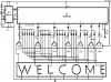
I have built a knight rider type circuit using a 555/74193 and 74154.
I have used half of the o/p's of the 154 to "count up" and the second half to "count down"
This works fine if all you want to use is 1 or 2 led's, lighting each one in turn like "kitt" does in the tv program.
In this configuration the circuit will light 1 led in turn and extinguish the one it has just lit, etc up to nine and then repeat itself.
See attached schematic.

I have been given an idea that will do the complete opposite to the above IE
LED1 is off and the rest are ON
LED2 is off and the rest are ON ,,,, etc up to LED9 then it repeats.

Can anyone give me an idea how to achieve this idea and it has to be capable of driving between 13 and 17 LEDS.

The reason for so many LEDS is that they will make up letters of the alphabet.

I have found many schematic’s that will light multiple LEDS in a switch on configuration but NONE that will keep them on with a momentary OFF

CAN anyone HELP me PLEASE

PLZ reply with a schematic as I find them easier to follow

Many thanks in advance Steve
 

Attachments

  • 16 LED knight rider.JPG
    16 LED knight rider.JPG
    115.8 KB · Views: 1,109
Last edited:
Hi , thanks for the reply but if I read the SCH right it does not give me the amount of outputs that I require.
To put my skills in context,, I can follow and build circuits but not design them

Cheers Steve
 
Hi , thanks for the reply but if I read the SCH right it does not give me the amount of outputs that I require.
To put my skills in context,, I can follow and build circuits but not design them

Cheers Steve

The additional outputs would be achieved by using say 2 LS193 is series and 2 LS155 i/c's.

Have you done a forum search for Knight rider type circuits.?

Displaying the letters of the alphabet would not be posssible using your method.
 
Last edited:
Thanks for the reply
I have been looking through "some" of the circuits on the site and via a google search and can find nothing that may come close
to what I want after you said that using what I have will not work.

I am prepared to start fron scratch but would need some idea of what will work.
Can you please point me in the right direction or even show me a SCH that will work.

Thanks inadvance Steve

Steve,
You should decide that you want alpha characters displayed or a simple sweeping LED bar.

For alpha you will need a 'decoder' ic or use a PIC to create the alphabet characters.

A 'kitt' type of sweeping LED bar can be achieved using logic ic's.
 
Hello Eric ,, thanks for the reply.
This reply comes in two parts
FIRST
I have found the diagram that sparked this whole idea off ,, thing is I cant get it to work with more than 2LEDS. Could you have a look plz and tell me if it works or not.
Second the info and SCH
 
Here's the SCH
 

Attachments

  • led sign welcome.JPG
    led sign welcome.JPG
    232.1 KB · Views: 846
Last edited:
Here is a running message display circuit wherein the letters formed by LED arrangement light up progressively. Once all the letters of the message have been lit up, the circuit gets reset. The circuit is built around Johnson decade counter CD4017BC (IC2). One of the IC CD4017BE's features is its provision of ten fully decoded outputs, making the IC ideal for use in a whole range of sequencing operations. In the circuit only one of the outputs remains high and the other outputs switch to high state successively on the arrival of each clock pulse. The timer NE555 (IC1) is wired as a 1Hz astable multivibrator which clocks the IC2 for sequencing operations. On reset, output pin 3 goes high and drives transistor T7 to 'on' state. The output of transistor T7 is connected to letter "W" of the LED word array (all LEDs of letter array are connected in parallel) and thus letter "W" is illuminated. On arrival of first clock pulse, pin 3 goes low and pin 2 goes high. Transistor T6 conducts and letter "E" lights up. The preceding letter "W" also remains lighted because of forward biasing of transistor T7 via diode D21. In a similar fashion, on the arrival of each successive pulse, the other letters of the display are also illuminated and finally the complete word becomes visible. On the following clock pulse, pin 6 goes to logic 1 and resets the circuit, and the sequence repeats itself. The frequency of sequencing operations is controlled with the help of potmeter VR1.
The display can be fixed on a veroboard of suitable size and connected to ground of a common supply (of 6V to 9V) while the anodes of LEDs are to be connected to emitters of transistors T1 through T7 as shown in the circuit. The above circuit is very versatile and can be wired with a large number of LEDs

Hope this all makes sence coz I'm getting lost with it. Steve
 

Attachments

  • led sign welcome.JPG
    led sign welcome.JPG
    232.1 KB · Views: 238
Last edited:
Hello Eric ,, thanks for the reply.
This reply comes in two parts
FIRST
I have found the diagram that sparked this whole idea off ,, thing is I cant get it to work with more than 2LEDS. Could you have a look plz and tell me if it works or not.
Second the info and SCH

hi Steve,
The LEDs that you are using have you forward voltage matched them.?

When you say 2 LED's I guess you mean just 2 leds in each character or is it 2 full characters, eg: WE....?

What are you using for the power supply to the project.?
 
Hi ya Eric , again thanks
No I have not forward matched them (whats that)
yep that just 2 LEDS on each character letter before they go dim (either in parallel or series)
A mains transformer 36-0-36 using one side of it through a bridge rec and other bits controled by a LM317 set at 9.01v according to the digital avo
Thanks for taking the time to help me Steve

hi,
As the transformer is 36Vac, after rectification this will give about 50Vdc!!!
I believe as the current is increased in the parallel LED's your LM317 is heating and going into shutdown. The LM317 is rated at 37Vdc max.

Matching LED's: the same colour LED's can have different turn voltages, varying about 0.2v thru 0.3V, so the lower forward LED will draw more current than the higher forward ones.
 

Attachments

  • LEDfwd1.gif
    LEDfwd1.gif
    6.1 KB · Views: 184
Last edited:
thanks for the info Eric
I will check 2moro and see what the voltages are
As ut stands at the moment the floor of the box is only getting warm
maybe its a bit more than warm BUT its no where near hot
Hope to post info 2moro
Thanks again for the help
Cheers steve
 
HI there Eric
I have check the voltages and your right
Transformer O/P 34.8 V-ac
At the bridge rec 47.6 V-dc
O/P 9.01V-dc
Current draw at circuit board between 0.66A and 0.21A or 0.27A err i did see it properly (aprox)
Current draw at LED board which has 3LEDS per output draws between 0.71A and 0.08A that I did see .(aprox)
I cant se the print on the transistor properly but it was sold by maplins as a LM317, so I asume thats what it is.
I have had it running this morning inbetween the kids and shopping and it still only get warm.
Have just gone back to it after about 1 hour and the flaming thing is "HOT"
Sorry u where right but this is the first time its got this hot
Hope this helps LOL ,,, it dont help me
Time for a rethink and may I please get in touch with reference the LM and this darn circuit
Again thank ,,, Steve

hi Steve,
I would suggest a 9Vdc 1Amp 'wall wart' or 12Vdc 1A if you want to use a LM317 which should be mounted on a heat sink if it starts to get HOT.
 
Hi there Eric
The LM317 has its own heatsink. Its mounted to the bottom of the metal box (its just over 1mm thick) that houses the transformer
I asume you mean a wall mounted PSU (phone charger type)
The attatched gif is a crude from of the effect I am after ,,,, and the two names are my grand kids who where,,,, never mind long story ,, no gonna bore u with it.
I forgot to put on my profile that I live in the UK "opps"
How do I go about asking "you or anyone" for help designing a circuit that looks something like the gif??
Cheers in advance
Steve
 

Attachments

  • movin.gif
    movin.gif
    63.9 KB · Views: 186
Last edited:
Status
Not open for further replies.

Latest threads

New Articles From Microcontroller Tips

Back
Top