Continue to Site

Welcome to our site!

Electro Tech is an online community (with over 170,000 members) who enjoy talking about and building electronic circuits, projects and gadgets. To participate you need to register. Registration is free. Click here to register now.

  • Welcome to our site! Electro Tech is an online community (with over 170,000 members) who enjoy talking about and building electronic circuits, projects and gadgets. To participate you need to register. Registration is free. Click here to register now.

Help with sum logic gates n..........

Status
Not open for further replies.

umer007

New Member
Can sumone plz gimme an electrical analogy for NAND gate, NOR gate and a XOR (EOR) gate plz. By electrical analogy i mean a ciruit diagram that describes how the gate works.

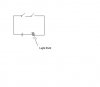
I am tryint to attach an example of a AND gate i made on Paint but it said bmp not allowed or sumthin. Plz tell me how to post so i can show u a example or if u know wt im talkin abt plz answer post.

TYVM
 
jpg format is acceptable, you need a scanner or bmp converter.

This is my anolagy for the gates:
 

Attachments

  • LOGIC_144.jpg
    LOGIC_144.jpg
    23 KB · Views: 567
A and B are the input to the descrete logic

C is the output

Also altough you asked fo r NAND,NOR,XOR the simplest gate AND and OR can be made from two diodes and a resistor - although can only have a fanout of 1
 
I wz wonderin if u cud gimme a analogy in the form of a circuit that is attached.
 

Attachments

  • thing.JPG
    thing.JPG
    6.3 KB · Views: 324
umer007 said:
I wz wonderin if u cud gimme a analogy in the form of a circuit that is attached.

The circuit you attached is an AND gate using switches. If you label the switches A and B, then the lamp glows when A AND B are closed.

If you put the switches in parallel, you have an OR gate. The lamp glows when A OR B (or both) is closed.

To create an analogue of a NAND gate using switch contacts, connect 2 normally closed switches in parallal. Thus the lamp does NOT glow when both switches are operated.

To draw circuits for this forum, I draw them in PowerPoint and then save them as a .gif file. This file can be attached to a post.

Len
 
umer007 said:
Yes i know but i need NAND, NOR, EXOR in that kind of drawing. Plz post if u know.

I think you posted this while I was editing my previous post to describe a NAND analogue.

A NOR analogue would be 2 NC contacts in series. So the lamp does NOT glow if A OR B is operated.

I'll draw a XOR and post is shortly.

Len
 
Here are a NAND, NOR and XOR gate. I'll leave you to draw the lamp and battery.

NAND - lamp does NOT glow if A AND B are operated

NOR - lamp does NOT glow if A OR B are operated

In the XOR case, the lamp glows when A is operated or when B is operated but NOT if both are operated.

This is how lights in houses can be controlled by 2 switches.

Len
 

Attachments

  • Gates_172.gif
    Gates_172.gif
    1.9 KB · Views: 454
Status
Not open for further replies.

Latest threads

New Articles From Microcontroller Tips

Back
Top