Continue to Site

Welcome to our site!

Electro Tech is an online community (with over 170,000 members) who enjoy talking about and building electronic circuits, projects and gadgets. To participate you need to register. Registration is free. Click here to register now.

  • Welcome to our site! Electro Tech is an online community (with over 170,000 members) who enjoy talking about and building electronic circuits, projects and gadgets. To participate you need to register. Registration is free. Click here to register now.

Help with simple voltage/current sensing relay.

Status
Not open for further replies.
Based on what you've told me so far you should be able to wire it directly.
 
What is the "current transfer ratio"

What do you think i need? can you point me to a unit you think would work better?

What about the first unit posted?

thanks again
 
I'm not entirely sure about this, I honestly don't know enough about the practical circuits involved, but you may be able to get away with using a single NPN transistor. Feed the 4.6 volt signal into the base. Connect the collector to +12V and connect the emitter to the ECU input. Pretty much any NPN transistor will do.
 
Last edited:
wow this is getting complicated (for me anyways)

i thought the 4.6v 5 mA signal would just close the "switch" allowing the 12v 21 mA the ecu needs to pass through the other side to the ECU

:/
 
How can i ID an NPN transistor? I have a few broken electronics (dvd player and now a phone) with a bunch of transistors in them.

I'd like to try this
 
That's what I think the single transistor should do, the problem is I don't know what type of output your AC switch actually is, or what type of input your ECU actually takes, the circuit components on the other side of those wires makes all the difference, and I'm just not that good at the practical side =) I'm surprised other users aren't chiming in here. I'd try the single transistor, it's something you can pick up at radio shack for less than a dollar.

If you can get a discrete transistor out of an old device the website I'm linking bellow tells you how to determine what the base/collector/emitter leads are. If you don't get results consistent with what it says try another transistor as the one you're checking could be PNP

Multimeter test for diodes and transistors :: Electronics and Radio Today

The side labeled bc182 is what a typical small signal transistor looks like. BUT the collector emitter base pins may be different, that's what the above link is for determining.
**broken link removed**
 
Last edited:
I found one that tested as a NPN transistor and hooked it up as you described.

It didn't work (didn't let any power through) and testing it afterwords indicates a bad transistor (blown through, bad readings)

I think the full 12v from the car is too much for the transistor ... maybe a resistor is needed before it?

Not sure what to do next. Thanks for all the help so far.
 
I'm not entirely sure about this, I honestly don't know enough about the practical circuits involved, but you may be able to get away with using a single NPN transistor. Feed the 4.6 volt signal into the base. Connect the collector to +12V and connect the emitter to the ECU input. Pretty much any NPN transistor will do.
That won't work. What you are describing is an emitter follower. The emitter voltage will never get higher than 0.7V below the base, or about 3.9V, in this case.
 
If you want to use transistors, you can do it like this.
You can use almost any general purpose transistors, as long as you mind the type (NPN, PNP).
 

Attachments

  • voltage translator.PNG
    voltage translator.PNG
    10.9 KB · Views: 221
Last edited:
The resistor divider on the NPN's gate lowers the 4.6 volts bellow 500mv, the base junction never becomes forward biased. If you skip the 10k and 1k resistor divider on the base and just use a 1k resistor to the base it works fine. What's the resistor divider for?

I was hoping the single NPN would provide a low enough impedance compared to the existing AC switch signal that it might trigger it, I'm shooting in the dark here as I don't know how to determine what type of input/outputs those are though. As I said I'm not so good at the practical side of things. If Sketch can find an NPN and PNP transistor and a few resistors he should be able to replicate your circuit, with a single 1k to the base of the NPN instead of the 10k + 1k to ground.

I played around with it a little more, for simplicity sake the 3.9k resistor can be replaced with a 1k doesn't alter anything in the simulation I ran
With 4.6 volts in and using a 600 ohm resistor as a load (which matches the current draw he's getting directly shorting the 12V to the ECU) I'm getting a nice clean 12V signal.

Hopefully Sketchy can put that together. You can probably get all the parts off of old boards, for assembly though I'd buy a small piece of perfboard to solder it to.
 
Last edited:
Here's a screen capture of what I simulated, after altering it.
Just about any NPN or PNP transistor should do.
 

Attachments

  • transistor level shifter.png
    transistor level shifter.png
    63.3 KB · Views: 187
Last edited:
I'm not entirely sure about this, I honestly don't know enough about the practical circuits involved, but you may be able to get away with using a single NPN transistor. Feed the 4.6 volt signal into the base. Connect the collector to +12V and connect the emitter to the ECU input. Pretty much any NPN transistor will do.

an emitter follower will only output the base voltage minus 0.6 or 0.7V, i.e. 4V

try something like this, no relays required..... just about any NPN and PNP transistor will do. the input resistor can be anything from 100 to 470 ohms, and the other two resistors can be anything from 1k to 10k.....
 

Attachments

  • ecu_shifter.jpg
    ecu_shifter.jpg
    33.5 KB · Views: 195
Last edited:
New information:

It doesn't just need 12v.

I tried 12v through a 680 ohm resistor and it won't click on. (~21 mA?)

Then I tried through a 450 ohm resistor and it DOES click on. ( ~30 mA?)

So there are some power requirements. Do those circuits give enough power?
 
scad.... we must have started typing at the same time..... and i was drawing on the fly, so you got there first.....
 
Uncle's last schematic should work just fine, given what you've stated so far I don't think the 470 ohm gate resistor is NOT required though, use it at first remove it if it doesn't work. The voltage isn't incredibly sensitive, generic NPN/PNPs will be well within a car voltages range.
 
Last edited:
an emitter follower will only output the base voltage minus 0.6 or 0.7V, i.e. 4V

try something like this, no relays required..... just about any NPN and PNP transistor will do. the input resistor can be anything from 100 to 470 ohms, and the other two resistors can be anything from 1k to 10k.....
That's guaranteed smoke.:D 
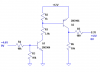
You don't have any current limiting between the collector of the NPN and the base of the PNP.
 
Status
Not open for further replies.

Latest threads

New Articles From Microcontroller Tips

Back
Top