Continue to Site

Welcome to our site!

Electro Tech is an online community (with over 170,000 members) who enjoy talking about and building electronic circuits, projects and gadgets. To participate you need to register. Registration is free. Click here to register now.

  • Welcome to our site! Electro Tech is an online community (with over 170,000 members) who enjoy talking about and building electronic circuits, projects and gadgets. To participate you need to register. Registration is free. Click here to register now.

Help with simple logic

Status
Not open for further replies.
I found relays drawing 28mA, but the 4043 can't handle that directly?
No.
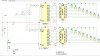
As shown from the data sheet below, the output is only 1 mA typical for a 5V supply.
You can use the ULN2803 or a 2N7000 MOSFET as a driver for the relay.

The MOSFET will also require a diode for inductive transient suppression from the relay coil.
The ULN2803 has that diode built-in.

1553892684962.png
 
Last edited:
No. You still need a small transistor driver per relay. The ULN20xx and ULN28xx series are designed from the ground up to be a bank of 7 or 8 relay drivers. They include base current limiting resistors, base pull down resistors, and output suppression diodes - all the bits and pieces that make 8 individual circuits a pain. The 2803 is for 5 V systems. The 2804 is for 12 V systems.

Edit: Wally's response showed up after I posted.

ak
 
Hi

Here's another version using CD4017B's.
The circuit powers up with all relays deenergized.
The 1v,0V level on the graph represents the energized, de-enegized state of each K1,K8,K9,K16 relay, respectively.

eT

1553916792866.png


1553916842129.png
 
Don't think so. The requirement is for 16 buttons that can randomly select any relay at any time.

ak

I don't see in any post anything about a random selection requirement. It makes sense though.
But yes...this would be sequenced.

eT
 
Thank You everyone for Your help, especially crutschow. I have ordered components and I'm going to use your schematic.
At first my idea was to use breadboard, but maybe I should start making my own.
It was rather a long time since I made circuit boards, but I have a UV-box. What is the simplest way to create your own boards these days?
I remember using specially coated boards in the UV-box, and etching with somethimg ferro-oxide!? The most troublesome part was to get the drawing onto the board, as I recall. Does anyone have a tip?
 
Yes, if you've done the UV process...
Assuming you have drawn a board on a computer file...

1) find some clear PET film (overhead transparency)
2) print two copies with a laser printer
3) tape the transparencies to a piece of glass (carefully stacked) with toner side away from glass
4) use a sensitized copper clad circuit board (MG chemicals - available on Amazon)
5) cut board to size (band saw, utility knife or other
6) remove protector film from board and set against toner side of clear PET on glass
7) tape the board to the glass and clamp a second piece of glass to the first with binder clips to keep everything tight.
8) expose for some minutes (I don't know how strong your UV box is)
9) then dip the exposed board into the MG circuitboard developer (diluted into 8 parts water)
10) rinse
11) etch the copper away with ferric chloride - this will stain anything it touches.
12) rinse.
13) drill with 0.8, 1mm and 1.2 mm bits - depending on your parts

Or... send the drawing off to PCBWay or dirtyPCB.com or ...
And get a stack of boards for $50 or so.

If you would DIY, You should expect to spend
$10 on bits (I assume you have a drill)
$15 on developer
$15 on ferric chloride
$15 on sensitized pcb (you may need several to get the exposure time right)
$10 on a stack of transparencies
$5 on glass plates
A couple hours gathering your supplies, depending on the mess you make and sink yo damage with ferric chloride...

Good luck
 
I would recommend doing a breadboard of at least a couple stages, just to make sure works as desired, before you do the PCB.
 
This schematic looks really good!
I have two questions.

#1. I will be using this together with ULN2803 as relay driver with 12V relays. And it would be nice to run everything on 12V including the Radio-Button NAND gate circuit. So the ULN2803 used here looks to be suitable for 5V TTL and CMOS and then I found the ULN2804 that's for 6-15V CMOS. Is that the one I want for a 12V version of this schematic? So if I use ULN2804 with 12V instead of ULN2803 (5V) can I still use the same values on the resistors and the capacitor used in this schematic?

#2. Is the switch a SPST switch?

Thanks


Here's an LTspice simulation of the NAND gate circuit with write-up here.
Only the output with the last pressed switch is active.
Each output, with an added transistor driver, or a driver IC such as the ULN2803, can control a relay.
The circuit can be extended to 16 outputs by duplicating the right portion of the circuit consisting of a diode, two resistors, and two NAND gates.


1552618661051-png.117183
 
Last edited:
I found the ULN2804 that's for 6-15V CMOS. Is that the one I want for a 12V version of this schematic? So if I use ULN2804 with 12V instead of ULN2803 (5V) can I still use the same values on the resistors and the capacitor used in this schematic?
Yes.
Is the switch a SPST switch?
Yes, it's a SPST momentary push-button switch.
 
Yes.
Yes, it's a SPST momentary push-button switch.

Oh sorry just realized I mixed things up in my question. What I wanted to ask is: Can I power the CD4011 in your schematic with 12V and still use same values on the resistors and capacitor. Thanks!
 
Yes. The power-on-reset pulse will increase to around 2 seconds. You can shorten it by decreasing C2. Other than that, everything else will function the same way.

ak
 
Don't think so. The requirement is for 16 buttons that can randomly select any relay at any time.

ak

This may work with 4017 for 16 switches selectable. Every time there will be a very short duration pulse passing through the outputs, may not change the status. otherwise it may need a RC / RL delay. Hope replays' mechanical response time will do that. just sketched over Tom's schematic.

Edit: may need some improvement
 

Attachments

  • 4017 as radio switch.jpg
    4017 as radio switch.jpg
    901.9 KB · Views: 179
Last edited:
Status
Not open for further replies.

New Articles From Microcontroller Tips

Back
Top