Continue to Site

Welcome to our site!

Electro Tech is an online community (with over 170,000 members) who enjoy talking about and building electronic circuits, projects and gadgets. To participate you need to register. Registration is free. Click here to register now.

  • Welcome to our site! Electro Tech is an online community (with over 170,000 members) who enjoy talking about and building electronic circuits, projects and gadgets. To participate you need to register. Registration is free. Click here to register now.

Help with reversing polarity to run common anode LED's

Status
Not open for further replies.

booliminator

New Member
Hey,
I want to control my 3 color common anode LED's using my arduino but I dont know how to do this.
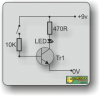
If I have the anode to +5v, how do I control the negative legs using an arduino?
Ive heard of current inverter IC's, but is there any way to do this with regular components like transistors, resistors, and capacitors?

Thanks
 
Hi,

Depending on the current requirements of the LEDs, you can connect them directly to the Arduino pins with a series resistor of perhaps 330 ohms (for ~10mA drive current). Setting the pin low will turn on the LED. You can also use PWM to drive them if you wish to change the brightness.

If you need more current than the arduino output can provide, you can buffer the current using a transistor as shown in the attached image (obviously you can use a 5V power supply and a different resistor). The arduino output pin goes in place of the switch in the picture.
 

Attachments

  • LED%20transistor%20driver.png
    LED%20transistor%20driver.png
    23.3 KB · Views: 155
On the arduino forum they say that arduino will sink and source the same amount of current. (many micros can pull to ground better than pulling up to supply) So there is no advantage to common anode or cathode.

Like Dougy said use a resistor from micro to LED. (three resistors in your case)

The common pin goes to VCC (common anode) or GND (common cathode).
 
Why not use an inverter or whatever because they take up less space. A ULN2003 or similar device is a 7 channel device. You can get 8 channel devices (different p/n). It also may depend on the logic levels used.

You will also require a series resistor for each segment.
 
I've written software for a pic for a common cathode 7 segment, and then used it on a common anode, and rather than totally re-write the lookup table I just inserted a comf instruction just before I write the bit image to the o/p port to turn on the leds, comf just inverts all the bits within the byte.
The arduino probably has a similar instruction.
 
Status
Not open for further replies.

Latest threads

New Articles From Microcontroller Tips

Back
Top