Continue to Site

Welcome to our site!

Electro Tech is an online community (with over 170,000 members) who enjoy talking about and building electronic circuits, projects and gadgets. To participate you need to register. Registration is free. Click here to register now.

  • Welcome to our site! Electro Tech is an online community (with over 170,000 members) who enjoy talking about and building electronic circuits, projects and gadgets. To participate you need to register. Registration is free. Click here to register now.

Help with relay logic controlling a home brewery

Status
Not open for further replies.

KVS

New Member
Hi all,

I'm new to this forum and hope that you can help me. I'm in the process of building a control cabinet for my home brewery. The brewery consists of three heating elements (3500W) but I only have available two 16A power feeds (220V, living in Norway).
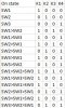
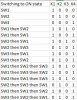
The heating elements are controlled by 4 contactors, K1, K2, K3 and K4, where K2 & K3 are for Heater 2. To control the 4 contactor I have three switches, on my drawing showed as NO, but can I can add more NC or NO to these.

I've created a logic on how this should work, with switching sequence in left column. The main areas of concern is that K1&K2 must never activate at the same time. This also applies to K2&K3 and K3&K4. All the contactor have additional 1xNO and 1xNC that can be used. If needed I can also add more relays. The control voltage for the contactors are 24VDC.

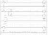
Attached is also a ladder diagram showing my thinking, but I'm stuck. No matter how hard I try I'm not able to solve this, it has been too long since my electronic exams.

Maybe not a very good description, but I hope it's understandable.
I'm very grateful for any help, my brewing of beer depends on this ;)
 

Attachments

  • Ladder diagram.jpg
    Ladder diagram.jpg
    100.1 KB · Views: 219
  • Logic.jpg
    Logic.jpg
    50.3 KB · Views: 182
Looking it over briefly it appears you actually have 6 state/combo's for the four relays, it might be simpler to use a 4 wafer 6 posn rotary switch, especially if not using an actual PLC.
You could then set the 6 binary states to pick up the four relays, you would need a break before make type.
Max.
 
Are you looking for a circuit to step through the 15 conditions automatically in sequence, or some interlock logic to prevent inadvertent unwanted conditions under manual control, or what?

Also, what is the contactor coil current (assuming they all are equal)?

ak
 
Actually I only count 6 combo's?
The other 5 are just duplicates, the Custom wired Hex switch also takes care of the interlocking.
A Hex thumb wheel switch would also do it but wasted positions, and intermediate relays would be needed.
Max.
 
Last edited:
Thanks for your replies, been busy elsewhere so late answering.

A rotary switch would likely solve the proble, but the cabinet is already made and parts purchase, so I'm stuck with the three switches. That said, the switches are of the telemcanique type and can be extended with several NO and NC. They are all break before make type.


Are you looking for a circuit to step through the 15 conditions automatically in sequence, or some interlock logic to prevent inadvertent unwanted conditions under manual control, or what?

Also, what is the contactor coil current (assuming they all are equal)?

ak
I'm looking for an interlock logic to prevent overload and short circuit. All the contactors have coil voltage of 24VDC.

I have attached two more images hoping to explain better.
 

Attachments

  • Logic-2.jpg
    Logic-2.jpg
    62.3 KB · Views: 164
  • Brewery.jpg
    Brewery.jpg
    68.7 KB · Views: 200
According to your schematic, closing S2 connects two separate AC power sources directly together. This is bad.

ak
 
It would seem to me that you are wishing to select 6 conditions with three switches?
Are you using a PLC?
If so what model??
Max.
 
A rotary switch would likely solve the proble, but the cabinet is already made and parts purchase, so I'm stuck with the three switches.

So the system design was finalized before the logic was confirmed?
I usually work in the reverse!
If it is a home based, one-off I would have thought that it would be more than slightly flexible!
Max.
 
Last edited:
Thank you for your replies. I was originally having three AC inputs, but this will not happen, so hence trying to do the "same" job with two.
It is a one of build and home based. I could have made it all simpler, but i like to challenge myself and I want it to be safe.
I understand now that doing what I want just with switches and contactor will be difficult so I've started looking into using a PLC. Most likely I will use a Siemens Logo 24RC, but this time I will confirm the logics before purchase :)
 
One very simple way, but requires observance of correct sequence is to have a master/arming switch for the 24v coil supply, then use four switches for the 6 states, this would require operate arming sw off, then set the required switch state/4 bit pattern.
Then Arming on.
Go through the same sequence for changing state, arm off first.
Max.
 
Last edited:
Thank you all for your inputs, it has been a great help.
I ended up using a Siemens Logic 8, and after a steep learning curve in "PLC" programming I managed to achieve what I intended.
 
Status
Not open for further replies.

Latest threads

Back
Top