Continue to Site

Welcome to our site!

Electro Tech is an online community (with over 170,000 members) who enjoy talking about and building electronic circuits, projects and gadgets. To participate you need to register. Registration is free. Click here to register now.

  • Welcome to our site! Electro Tech is an online community (with over 170,000 members) who enjoy talking about and building electronic circuits, projects and gadgets. To participate you need to register. Registration is free. Click here to register now.

help with "metering" a Jacob's Ladder

Status
Not open for further replies.

bzapper

New Member
Boy am I glad I found this site!

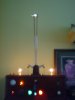
Brief background: I am building a new display for the local Museum of Radio and Electricity as a volunteer. The Jacob's Ladder will be powered by a standard neon light transformer. I have several available, so the output voltage might be 9K, 12K, or 15K AC.

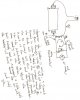
I have a rough schematic supplied by the Museum's owner for a circuit that will power a volt meter to add an effect of "pegging" the meter each time the Ladder fires. What I don't know and won't know without your help and/or a lot of experimentation (which is OK, but tedious) is how many turns of wire should I wrap around the HV output wire to induce a current that will then be rectified and read by a DC volt meter?

I hope I have explained this sufficiently, as I am only an amateur who has managed to survive this long messing around with electricity only by the grace of God...

I am happy to expand on this explanation, if necessary, but wanted to avoid the MEGO symptom in my readers.

I would appreciate any and all advice, including wire gauges, etc.

(The Ladder will resemble a Steam Punk device with flashing lights and a motion sensor...)

Yours eternally, bzapper

p.s. I realize I'm mixing my terms talking about "inducing a current" to be read by a "volt meter." Please forgive me. I want to use a DC volt meter.
 
Last edited:
I have built several Jacobs ladders. Is yours going to be for display?

Any of those voltages you listed will work but 15k will work best, start easy, produce the best climbing arc, and be most impressive for display.

Your Jacobs Ladder produces a magnet attraction between 2 long wires as the arc travels up the wires start moving back and forth. Each time the arc travels to the top the wires wave back and forth they get closer and closer together until they finally touch and short out the transformer. The best solution for this problem is go to your local welding supply shop and buy 2 brass welding rods 1/8" diameter 3 feet long to build your Jacobs Ladder. Anchor both top and bottom ends of each rod so they will not move on their own.

Air movement affects the arc so the Jacobs Ladder works best inside of an enclosed space like a clear glass or plastic tube or box. As I recall the arc will jump about 3/8" maximum on a 15KV transformer so your 2 brass rods need to be slightly less that 3/8" apart at the bottom. Max length of the arc is about 2" to 2.5" most of the time depending on air humidity and other things so set the brass rod spacing at about 2.5" at the top. Fix your brass rods so they can be adjusted closer or farther apart for fine tuning. If the arc will not start at the bottom the brass rods need to be closer together. If the arc starts fine at the bottom but the arc will not climb up the rods the rods are too close together at the bottom. If the arc never goes all the way to the top the rods are too far apart at the top. If the arc goes all the way to the top and stays there the rods are too close together. Round off both ends of the brass rods to a ball shape you do not want any sharp edges. Solder your wires to the outside surface of the brass rods if any solder gets on the inside file it off again no sharp edges or sharp points. The transformer is connected directly to the brass rods with HV wire.

You need an AC volt meter with a resistor if you want to read the voltage. 15 volt or 150 volt movement meter with the correct resistor will work great.

I have built a lot of High Voltage things including 7 or 8 Tesla Coils each one larger or smaller than the others. Here is my 10" TC is makes 12 foot long arcs and sparks running on a 12KW transformer. It produces a 27 ft circle of lightning in the back yard.

**broken link removed**

**broken link removed**

**broken link removed**
 
Last edited:
I think you want a meter, not to read 15kv, but to read "over voltage". (full scale, off the meter, pegged, too much...)
Can you post the rough schematic?
Do you care if the meter is reading voltage or current?
Do you have the meter yet? What meter? (analog)
 
The simplest method would be to just read the input amps on the primary side and stay away from the HV secondary all together.

A no load condition will give you a low amp draw but once the arc forms the amp draw shoots up considerably.
 
Thank you for the suggestions...

...but I still need an answer or advice, so here is the schematic, such as it is.

I want to follow this design first, but appreciate your alternative suggestions and may fall back on those if this proves unworkable.

The number of turns is the issue. The meter circuit wire will be coiled around the insulated HV feed wire, not the bare metal "antenna." I do intend to experiment with the suggestion to meter the amps on the primary side, as this sounds easy.

I have a few meters to chose from: all are analog, if I understand the term (not digital?).

DC amps 0-5
DC milliamps 0-20
DC volts 0-10
DC volts 0-3 and a second range on the meter face 0-15 which I do not understand as there are only two contacts, but a push button on the back (?)

If the schematic is hard to make out, just ask and I will explain. I also have the diode and the 10K pot.

The photo shows The Device, as I call it, on display in my office. I built this to my own design two summers ago, fulfilling a life goal, if you can believe it. The new Ladder will be on display at the local Museum of Radio and Electricity, which I will be happy to sneak you in for a tour when you're in town. They had not ventilated the old one, and it eventually ate itself from O3 concentration.

I just noticed on preview that the attachments are thumbnails, too small. How do I make them full-size for your convenience?

Little help?
 

Attachments

  • thedevice 003.jpg
    thedevice 003.jpg
    867.2 KB · Views: 540
  • metercircuit.jpg
    metercircuit.jpg
    225.3 KB · Views: 537
Oh, I see said the blind man as he picked up his hammer and saw... Click on the thumbnails and they GET BIG!

Who said "Never kick a fresh turd on a hot day"? (Hint: He was from my home state of Missouri.)
 
Neon transformers are shunt type transformers. It will be 30 ma or 60 ma. I am guessing you will use 30 ma no reason to have 60 ma a jacobs ladder does not need many amps. What your doing in the circuit drawing is making an air transformer. Coupling will be very low because its 60 Hz so doing the math is pointless. Your will need to experement. If you wind several turns of wire around a straight HV wire with no turns coupling will be extremely low and the meter movement is going to be very low too and that will be good it won't distroy your meter while you experement.
 
Last edited:
I would just build one of these. It would be a lot easier, and you could connect it directly across the terminals, so it can be put out of the way. That's my recommendation, anyway :D

Regards
 
Thank you, one and all. especially Gary350. The explanation was clear and now I'm off to the races (er, windings.)

I'm still open to suggestions in case any of you other bright lights want to chime in.

(Harry S. Truman made the remark, typical of a good ole' country boy...)
 
An other option to consider is using another neon sign TX rated for the same HV voltage as a step down VT.
A normal Voltmeter can be used to measure the 240 V terminals.
VT's are commonly used to measure substation transformers 33,000 Volts and lower.
The burden of your VT shouldn't affect the voltage to much as it is only supplying a volt meter.
 
I would just build one of these. It would be a lot easier, and you could connect it directly across the terminals, so it can be put out of the way. That's my recommendation, anyway :D

Regards

I Agree, A Voltage Divider is Best.
But you need some High Voltage types of Resistors.

I Have them if you want some!
 
Status
Not open for further replies.

Latest threads

New Articles From Microcontroller Tips

Back
Top