Continue to Site

Welcome to our site!

Electro Tech is an online community (with over 170,000 members) who enjoy talking about and building electronic circuits, projects and gadgets. To participate you need to register. Registration is free. Click here to register now.

  • Welcome to our site! Electro Tech is an online community (with over 170,000 members) who enjoy talking about and building electronic circuits, projects and gadgets. To participate you need to register. Registration is free. Click here to register now.

help with logic gate

Status
Not open for further replies.

themikestar

New Member
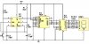
i am running 4 555 timers off the same 9v power source, but becuse each 555 timer runs a random number generator apparantly the frequency from each timer can leech to the next timer making it not random. I was told to use logic gates to fix this. How do i use logic gates to make each circuit totally independant ??.
 
multiple timers

apparantly the frequency from each timer can leech to the next timer

The only thing that comes to mind is noise getting coupled to an open FM pin (5), although this would seem to increase randomness. This pin can be used to frequency modulate the output, so it's a good idea to bypass the pin to ground with a 0.1uF cap. Also locate the timing components as close to the timer as possible.

Another way the timer can be affected is through switching spikes on the supply lines. If spikes occur when the RC level is near the 1/3 or 2/3 switching thresholds, the output frequency will jitter. Again, more randomness. Proper supply bypassing helps reduce this effect.
 
Are you using any bypass capacitors in close proximity to the 555 timers? I could imaging that some switching transients might be coupled to the other timers through the power supply.
 
the article i read says

"remember that the ne555, 4520 and all other logic IC's (such as logic gates) will work together so long as they are all using the same power supply-you could clock the counter from the output of a logic gate, for example."

is this correct ??

i am running 4 off the same power supply (random number generator) and a couple of times i have had the same number on all 4 displays, the chances of that happening a couple of times is fairly low, so i am not sure if the timers are all independent or if they are stuffing up.

below is the circuit i am using, i have 4 on the one power supply.
 

Attachments

  • COUNTER_152.jpg
    COUNTER_152.jpg
    54.3 KB · Views: 828
4 timers

Let me see if I've got this straight. You're running four of these circuits off of the same switch (S1)? and you have all of the reset pins (pin 4) tied together? If so, it's no surprise you get the same number on all 4 displays fairly often. It's the same circuit getting triggered at the same time, with the only "randomness" being in the tolerance of the timing components.

If this is the case, there's no frequency "leeching" going on between timers, your original post sounded a little suscpicious. Two things would help:

1) Increase the oscillator frequency to about 10Khz or greater. With the components shown, the timer outputs a 48Hz clock. The higher the frequency, the more random the result will be when releasing the switch. Of course, there's a point of diminishing returns.
F_osc = 1.44 / [(R1 + 2R2) x C1]

2) Vary the values of the timing components in each circuit. For example, run the timers at 8, 10, 12, and 14Khz.
 
Status
Not open for further replies.

Latest threads

New Articles From Microcontroller Tips

Back
Top