BigE4u
New Member
then maybe your supply was lower than 12V
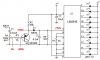
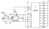
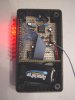
The circuit shown in my past post, for portability purposes, i made use of a 9V battery. I also made this same circuit first on a breadboard, but i used +12v and used the same resistor. I'll make sure to get ahold of a 68Ω 1w resistor next time i build this permanetly for my PC.