Electro Tech is an online community (with over 170,000 members) who enjoy talking about and building electronic circuits, projects and gadgets. To participate you need to register. Registration is free. Click here to register now.
Welcome to our site! Electro Tech is an online community (with over 170,000 members) who enjoy talking about and building electronic circuits, projects and gadgets. To participate you need to register. Registration is free. Click here to register now.
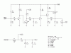
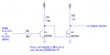
I am working on a demodulator for 25Khz PWM that will except 3.3 volt or 5 volt logic. The 12 volt supply is +/- 5%, the 3 volt supply will be from an IC zener. I would like some advice on selecting the transistors and help calculating the values of R5 and R6.
Your circuit does not make sense to me. Why is Q2 using a 3V Drain bias? As it is, Q3 will always be fully saturated in its ON state because base bias for that transistor will always flow through R9, R8 and R7 to the 3V supply or through Q2 to ground.
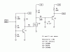
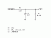
The circuit is overly complicated for what it does. It basically works, but would not be very stable over temperature. The emitter follower on the output introduces an offset due to the Vbe drop of the 3906, and the 100k pull-up resistor makes for a very high output resistance. I left out the gate resistor, and used 4.7K for the pull-up on the first stage. Attached is an LTSpice sim.
This is the output section. The control signal is from a 4-wire fan header, however implementation varies presently. I want to add a one size fits all input section. If there is a better way to condition the input , I would like to use it.
Your circuit does not make sense to me. Why is Q2 using a 3V Drain bias? As it is, Q3 will always be fully saturated in its ON state because base bias for that transistor will always flow through R9, R8 and R7 to the 3V supply or through Q2 to ground.
This should work. Q1 needs to have low storage time, thus the choice of 2N2369. If you can tolerate a little error, you can substitute 2N3904.
Likewise, leave out R3 if you can tolerate substantial error (you still have a 10k pullup in the output section).
The MOSFET can be any small N-channel (2N7000, 2N7002, BS123, etc.). The main requirement is Rds<<1kΩ. Don't use a big MOSFET, as the gate capacitance may screw up the duty cycle.
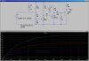
Yes. The problem with the 10k is, it is 10% of the 100k, so your charging time constant is 10% higher than the discharge time constant. This causes an error in the demodulated voltage. By putting the 1k in parallel, the error is less than 1%, and in my simulations, it appeared to be even lower. If you are building the output stage yourself, you can just use 1k instead of 10k for the pullup.
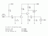
I did not even consider the time constant asymmetry, thanks for pointing that out Ron. I will be building the the whole circuit, changing the pull-up is not a problem. I do not have the tools for SMT, so I selected a PN2369A and a 2N7000 because they are available in a through-hole package.
Using a 1K pull-up opens a new can of worms for me. I originally decided on a LM4040 reference for the temperature stability over a regular Zener and I calculated the the 3 volt supply "seat-of-the-pants" with 90% headroom for a 10K pull-up. For a minimum supply of 11.4 volts, the limit resistor sets maximum current of 3200uA and the 4.7uF Tantalum was added to improve the output impedance at 25KHz. If I scale by a factor of 10 for the 1K pull-up, the current draw will be twice the maximum rating of the LM4040. How much headroom is actually needed?
Use a TL431/LM431 in place of the zener. That way you can set the current through R1 to be anything you want. Or use a LM317 with programing resistors to get 3.0V (or just use 1.25V as the reference voltage)
I don't see the problem. The 4040 works from 65uA to 15mA. Your load is zero to 3mA through the 1k resistor. Set the current through the reference bias resistor (r1 in your 4040 schematic) at ≈5mA when the supply is 11.4V ((11.4-3)/5mA=1.68k). Use 1.6k. If the supply is 12.6V, the total current will be 6mA. Zero to 3mA goes to the PWM filter. The rest goes through the 4040.
Thanks for the once-over on the LM4040. One of these days I should learn SPICE, but don't know if the learning curve is worth the infrequent use I would have for it. I added a pull-up at the input to set a default speed, if the control signal is missing the fan will run at full speed. Thank-you again for your time and insight.
This site uses cookies to help personalise content, tailor your experience and to keep you logged in if you register.
By continuing to use this site, you are consenting to our use of cookies.
")