Continue to Site

Welcome to our site!

Electro Tech is an online community (with over 170,000 members) who enjoy talking about and building electronic circuits, projects and gadgets. To participate you need to register. Registration is free. Click here to register now.

  • Welcome to our site! Electro Tech is an online community (with over 170,000 members) who enjoy talking about and building electronic circuits, projects and gadgets. To participate you need to register. Registration is free. Click here to register now.

Help with Countdown Lights

Status
Not open for further replies.
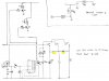
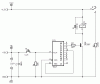
I can't get the 4017 to output enough power to operate either a lamp or a relay coil. I can get the output to switch on a transistor but I then burn up the transistor...

If you burn a transistor you certainly did a fatal mistake (e.g. too high base current). Please post your schematic with a transistor connected to a 4017 output.

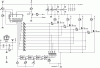
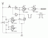
Also, could someone explain in layman's terms what the 74ls192 chip does? I can't find any good example circuits that use it and explain what's happening.

Thanks everyone!

The 74LS192 is a BCD up/down counter. Depending on the count direction (pin4=down, pin5=up) the counter value increases/decreases by the decimal value of 'one' with each clock pulse arriving at one of its inputs.

For your application with a fixed value to load into the counter you can load any number between 0 and 9 which will be displayed on a 7-segment display (with a BCD to 7-segment decoder driving the display) and counts down to zero where the counter has to be stopped from rolling over. (similar to the 4017 which counts from zero through nine and restarts if not stopped)

Boncuk
 
Last edited:
Attached is a schematic showing a single output and reset on 4.

Yes, that's the site. The clock is in this picture (and probably many others on the site).

**broken link removed**
 

Attachments

  • clock.jpg
    clock.jpg
    16.9 KB · Views: 220
That circuit can't work.

I didn't see the power supply for the IC. You must connect pin16 to +5V and pin8 to circuit ground. Don't omit the decoupling capacitor (C1, 100nF).

It won't be wrong to decouple the +12V rail as well using a 47 to 100µF electrolytic capacitor.

Using Q1 (pin3 for counter output) the relay will pull in after reset and remain pulled until you press S1 which advances the counter by one.

You did not use a free wheeling diode anti-parallel with the relay coil. Back EMF will kill the transistor most probably - if it hasn't died yet from excessive base current.

To properly clock the input (pin14) you must use a pull down resistor of 10KΩ. Pin13 (Enable) must be connected ground. Otherwise the counter is disabled.

You might save on the supply source of +5V by connecting the IC (pin16) to the +12V rail and also connect the push button to +12V.

When connecting the entire circuit to +12V increase the value of the base resistor to 6.8 .. 8.2KΩ.

Boncuk
 

Attachments

  • 4017-1-SCH.gif
    4017-1-SCH.gif
    12.4 KB · Views: 269
Last edited:
Yes, that's the site. The clock is in this picture (and probably many others on the site).
OK so thats the clock, it was cut off as well as the 2nd guy when I viewed the site.

The clock is portable and gets pluged in on site?
What kind of lights are you planing on using?

Andy
 
Boncuk; Can the OP use a cap in series with the trigger to debounce the switch.

Use the NC contacts of the light relays to keep them on and time off.

You will need another transistor and relay on the reset line for the motor.

Andy
 
Boncuk; Can the OP use a cap in series with the trigger to debounce the switch.

A cap in series with the trigger won't debounce sufficiently. See attached debounce circuit.

Use the NC contacts of the light relays to keep them on and time off.

Keep on what? It's impossible to count down with a decimal count up chip.

You will need another transistor and relay on the reset line for the motor.

Andy

The motor is running continously. Once it's started it will trigger the count-down circuit.

Using a BCD up/down counter with BCD to 7-segment decoder and a display is the easiest way.

Boncuk
 

Attachments

  • DEBOUNCE-SCH.gif
    DEBOUNCE-SCH.gif
    13.7 KB · Views: 344
Last edited:
Attached is a schematic showing a single output and reset on 4.

Yes, that's the site. The clock is in this picture (and probably many others on the site).

**broken link removed**

Where's the clock?

Boncuk
 
None of the ICs in this thread have a supply voltage shown on any schematic.
 
None of the ICs in this thread have a supply voltage shown on any schematic.

Mine have! Look sharp!

A small hint: The "thingy" labeled IC1P has pin numbers belonging to the IC, which are most probably supply pins since they are connected to VDD and ground. :)

Another small hint: Consult your eye surgeon. :D (Don't insult me!)

Boncuk
 
Last edited:
I am used to seeing the IC symbol having a power supply, not a "thingy" off to one side.
 
I am used to seeing the IC symbol having a power supply, not a "thingy" off to one side.

Good for you, but not for practical work.

The power supply is supposed to be drawn in a separate block within the schematic for a better view of the important things like signal nets.

You would probably realize more of those "thingies" if a schematic contains 20+ ICs. Just keep up with modern practice.

I had expected one word of excuse for having overlooked the power supply pins in my schematics :mad: instead of accusing me to post faulty circuit designs.


I do, too!
 
Last edited:
I don't remember seeing a pin for the power in the Yenka program (it's on my home computer, I'll check when I get home). So attached is a scan of a proposed circuit using Boncuk's design but including a few more lights. The clock itself is powered by a 12 volt car battery so if the 4017 can handle the 12 volts, I'd just as soon drop the 5 volt rail. I need to use lamps for the lights that are bright enough to see in daylight from 80-100 ft away. That might be 10-20 watts per bulb(???). Looking at my drawing, can I use diodes (D4 and D5 highlighted in yellow) set up like I have drawn? The logic is that when Q1 opens it powers K1 relay which then supplies power to all three lights (2 of them though the diodes). Then when the clock hand has made a circle and Q2 opens it trips K2 and supplies power to lamp 2 directly and lamp 3 though diode 5 but can't supply backwards to lamp 1 because of diode 4. I would want 4 lamps in total though.

Also does my clock motor start/stop circuit look ok?

Boncuk, the clock is that large white box in the lower right hand corner of the picture. It's analog and typically only used for a single revolution (1 min).

Thanks guys!
 

Attachments

  • Clock Circuit.jpg
    Clock Circuit.jpg
    73.1 KB · Views: 160
Last edited:
Hi Jfinch,

your circuit isn't quite correct.

I'll design a complete circuit for you. Arranging the light bulbs in reverse counting order you'll have a count-down indication.

Using appropriate coding of the outputs the light sequence will be: 4on - 3on - 2on - 1on - all off.

Boncuk
 
Boncuk; Thanks for helping the OP, I would have gone further but do not have the capablity to post schematics. Andy
 
Hi jfinch,

here is a circuit design which probably suit your needs.

It uses a Hall sensor mounted to the mechanical part of the timer. The timer must be fitted with a small magnet facing the sensor with its south pole. Each time the timer wheel passes the sensor the counter circuit will increase by one count.

The display works as follows: Starting the clock all four lights will be on, with three on after the first minute, two on after the second minute and so on until one light remains on. As soon as the second to last minute has elapsed all four lights will flash at a rate of approximately 1 second and flashing will cease when the counter has reached the count of five.

The timer is then stopped and has to be reset by reset button for a new race.

Attached are schematic and board design. The small baord contains the Hall sensor and has to be mounted with the sensor facing the clock wheel with the magnet.

Instead of using relays I preferred using logic level MosFet transistors which switch silently with no mechanical wear and tear. Additionally they are cheaper than relays. Their RDS(ON) is 9mΩ, meaning little voltage (36mV at 2A) loss for the connected light bulbs.

Regards

Boncuk
 

Attachments

  • COUNTDOWN-SCH.gif
    COUNTDOWN-SCH.gif
    27.6 KB · Views: 310
  • COUNTDOWN-BRD.gif
    COUNTDOWN-BRD.gif
    33.7 KB · Views: 132
Last edited:
Boncuk, you're awesome! That's more help than I was expecting. I like the solid state set-up using the FETs directly to power the lamps too. And I was thinking about using a automobile flasher relay to blink all four lights. You circuit is much cleaner. Thanks again. I might have a couple questions of clarification tomorrow when I get a chance to look closer at it, but currently my wife is telling me to get off the computer :) Merry Christmas all!
 
I don't see where the clock motor is controlled.

I assumed that it is already connected and running. If you don't have an accurate time base of one minute I'll change the design for an accurate digital time base.

Boncuk
 
Currently the clock only makes a single revolution and stops due to a mechanical limit switch. With a 5 minute countdown there needs to be some sort of logic to start and stop the clock motor. But I think I can figure it out using/modifying your circuit. Thanks again!

I wouldn't be against a digital based countdown, but I couldn't find any cheap large displays. Do you know where a large cheap display could be found? Could I make one from a bunch of LEDs?
 
Status
Not open for further replies.

Latest threads

New Articles From Microcontroller Tips

Back
Top