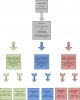
I have a project where I must control 3 different sets of valves that each contains 2 valves meaning I have 6 total valves. I have a flow of pressurized air up to 50 psi coming through a regulator and filter and this splits into two seperate tube lines which each lead into a valve. Each valve needs a supply of 10 volts and is current controlled. The valves need a maximum of 0.183A to be open completely and the valves are suppose to receive the same current at the same time.
I also have an oxygen supply coming in at 30 psi and I have it set up the same way with the same 10 volt valves that are current controlled. They each need a maximum of 0.183A to be fully open. Both sets of valves are going to work together to control the concentration of oxygen going into a box.
I have one last set of 2 valves that are electronically opened by applying 12 volts and 0.782A of current. These valves open under no pressure and are meant to act as release valves and are going to be either fully open or fully closed.
I am using Labview NI and an Elvis board to control the outputs going to the valves. There are two analog outputs that can be programmable to output a specific voltage and current at any time up too 15V and 500mA. I am using these two analog outputs to control the valves that are current controlled. The problem is I have two sets of two valves meaning I really need 4 connections when I only have 2 outputs from the board. I would like to keep the output needed from the Elvis to around 100 mA or less. I need a way to route the output of the board to a small circuit that can:
• Use a small amplifier that can be set to have a specific gain to magnify a smaller current sent out by the Elvis board. This current will be used adjusted through a program. If I have a separate power supply providing the 10V to the valves, what can I use to protect the Elvis board against inductive forces when the valves open and close? (I was previously advised about this problem that can occur).
• I was also advised to use solid state relays to solve this problem but I have never done anything with them so I have don’t know how they work. How can I use solid state relays to receive the input from the Elvis board controlled from Labview, and then control the current controlled valves by sending vary amounts of current from the Labview program. By sending varying amounts of current through a solid-state relay, will I get more or less current supplied to my valves? Do solid states relays only allow a set amount of current to be outputted up to its maximum, and that is whatever the load requires?
• Can I use a solid state relay to act as a switch either on or off and then have a programmable potentiometer or resister to adjust the current going to the valves?
I also need to be able to send a signal to the two release valves that require 0.792A each of current. This flow is either on or off. I can control a power supply output from the Elvis board to be on or off and have an output of up to 430mA. Would a solid-state relay work if it would provide up to 1.2 A of current within the range of its input voltage. So if I sent a voltage of 12V going to the relay and 12V going to the valve, and I have both valve wires connected to the output of the solid state relay, that can provide up to 1.5 A of current that operates between 3- 24V, will both valves get the required 0.792 A each?
I need to be able to make sure both valves get the required Voltage and current needed when the power supply is turned on.
I have attached a diagram of how the valves are set up..
I know this is kind of complicated but if you can give me any help, I truly appreciate it!
This is information about Labview and the Elvis board and its capabilities.
**broken link removed**
These are my valves:
Current Controlled 10V valves ( I have 4 of them):
https://www.clippard.com/store/byo_electronic/byo_proportional_valves.asp
Release Valves ( I have 2 of them) :
Link to data sheet:
https://www.electro-tech-online.com/custompdfs/2010/03/pg4243.pdf
Model ID: 827C12DCV
THANK YOU TO WHOEVER HELPS ME OUT!!
-------------------------------------------------------
Does anyone know of any power mosfets that can act as a gate for the 2 valves that need to be on or off.. a control signal can be sent to them around 5-7V to allow the power needed to open the release valves..
Attachments
Last edited:
