Continue to Site

Welcome to our site!

Electro Tech is an online community (with over 170,000 members) who enjoy talking about and building electronic circuits, projects and gadgets. To participate you need to register. Registration is free. Click here to register now.

  • Welcome to our site! Electro Tech is an online community (with over 170,000 members) who enjoy talking about and building electronic circuits, projects and gadgets. To participate you need to register. Registration is free. Click here to register now.

Help with Complex Schematic

Status
Not open for further replies.
Hello, new poster here. I am in desperate need of assistance :/

My professor gave us this schematic and wants us to build it. It's three SPDT switches, 1 momentary switch, some relays, fuses, a holding resistor, 4 lamps, wires, and a battery.

Here's the schematic
**broken link removed**

This project has me really nervous. Is it as difficult as I think it is?

P.s what value resistor should I use? Also, if anyone can help me in some way as to how I should connect this, that would be great. ANY help would be awesome. Thanks in advance.
 
From a connection standpoint you have all the information you need right there it's all in black and white. I'm not sure what the holding resistor is for though.
 
When the battery is first connected, lamp L-1 turns on (power goes from
battery through fuse F-1, across the NC contacts of relay p to lamp L-1)
When S1 is pushed, relay P is energized (coil already has a ground...power goes to point p-5 to energize relay) pulling down all three contacts.
This breaks power to lamp L-1 turning it off and now turns on lamp L-2 (power through F-1 goes across contact from p-1 top2 then lamp l-2)
Power also goes through P-3 and P-4 through the holding resistor. The holding resistor is connected to the relay coil which will keep relay P energized even after you release S1. (initially the resistor is energized from pushing S-1 but when you let go power is still energizing relay P through the holding resistor) This is called a holding circuit.

The rest is pretty point blank..just start with a light and try to draw back to find out how to make it come on. Look at lamp 4...it already has a ground so it only needs power from the battery to turn on...so follow from lamp 4 to relay V contact, then to fuse 3 and then to switch 2. so, now you know the only way lamp 4 will turn one is if you push switch 2!

Lamp 3 is a little trickier but not that bad. Lamp 3 also has a ground already and needs only power to turn on so draw back to the battery. First you go to switch s-3 (so you know you have to push that one to go to the next step) then you hit the normally open contacts of relay v...so you know in order for lamp 3 to come on relay v has to be energized so now look at how you have to get it energized. Following V's coil it goes up to the other relay near point p-2.....so relay P has to be energized because power is coming through fuse f-1 across point p-1 to p-2 then down to relay V. But V also needs a the ground through s-4 to energize. If you remember relay P can only be energized when switch s-1 is pushed....now think about what all that means....now you know relay V will never energize unless relay P is already energized.

Since lamp 3 is the most difficult we will run through its operation quickly.
(I would recommend drawing this on your schematic so you can see the flow of it easier) Pushing s-1 energizes relay P, power goes from Battery to F-1 to P-1 to P-2 then down to the top of relay V's coil. now remember you only have to push s-1 and let go and the holding circuit will keep power at V's coil. Now to get a ground to the coil to energize V you hold switch S-4.
Now the contacts get pulled down on relay V. so the N.O. contact is closed and the N.C. contact is open. So, now that V is energized you can push S-3 which connects the lamp to the top closed contact then it goes to fuse 3 and now you push s-2. lamp 3 turns on.

EDIT: attached are a few pictures.
 

Attachments

  • 1.JPG
    1.JPG
    92 KB · Views: 226
  • 2.JPG
    2.JPG
    95 KB · Views: 198
  • 3.JPG
    3.JPG
    95 KB · Views: 220
  • 4.JPG
    4.JPG
    96.7 KB · Views: 168
  • 5.JPG
    5.JPG
    97.6 KB · Views: 167
WOW! Thank you soooo much strokedmaro!!! ^_______^

I've been staring at the schematic all day and I think I have an idea of what Ihave to do.

I have 2 of these DPDT plug in Relays from Radioshack:

**broken link removed**


So from looking at it, it says that pins 1, 3, and 5 are normally closed? And pins 2, 4, and 6 are normally open? Or is it the other way around?

I only need these 2 relays right?
 
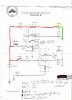
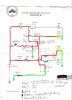
no....just like the schematic draw it out...the diagram on the relay shows pins 1 and 5 connected together (normally closed) and pin 1 and 3 are normally open...same thing on the other side 2 and 6 normally closed...2 and 4 normally open. pins 7 and 8 are the coil of the relay.

Just a heads up...this relay will work for both but wont look exactly like the schematic.
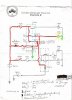
look at relay V...it has 2 contacts that are pulled by the coil....just like the relay in your picture which also has 2 contacts (the diagonal line between pin 5 and 1 would flow to the left when energized connecting pin 5 to pin 3)
Relay P however has 3 contacts...your relay only has 2.....but look closely at the schematic. The 3rd contact on relay P connects the holding resistor to the coil of the relay right? Well if all 3 contacts are pulled does it really matter if the holding resistor is connected to the 3rd or the 2nd contact? wouldn't power still get from fuse f-1 to the relay coil if the holding resistor were connected to point p-2 instead of p-4?

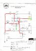
I want you to edit the schematic this time...erase the 3rd contact and connect the top of the holding resistor to point p2.

remember...schematics are 100% of the work...putting it together is the reward! Without a good schematic your project wont work as expected and your just wasting time. If you really understand and can draw out whats going on you'll be one step closer to building anything you can think of.

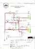
If you want to learn more try this....draw me a schematic that energizes the relay in the picture...you can draw the relay schematic exactly as it is in on the relay. connected the relay coil to ground and the other side of the coil to a switch...on the other side of the switch connect the battery...so when you close the switch the relay energizes. Now I want you to draw 2 lamp circuits...one light lamp should come on when the relay is energized and the other should come on when the relay is de-energized. If you can do that then you'll have no problem with your school project.

Dont worry if you draw it incorrectly the first time...we will all help you. I will look at what you post tomorrow and help you more from there... :) Dont worry...we all had to learn this stuff too with lots of mistakes along the way. Good luck
 
holding resistor value

Generally, relays pull in at 2/3 rds rated voltage and drop out at 1/3 rd. Since this circuit runs on DC, calculating this resistor value should be easy.

It would be a good idea to draw up the truth table for this network, as a 'sanity check'.
 
Last edited:
Professor?

Schematic?

What level is the course you're taking?

It looks pretty simple to me, typical 12 old level electronics.
 
Status
Not open for further replies.

Latest threads

New Articles From Microcontroller Tips

Back
Top