Continue to Site

Welcome to our site!

Electro Tech is an online community (with over 170,000 members) who enjoy talking about and building electronic circuits, projects and gadgets. To participate you need to register. Registration is free. Click here to register now.

  • Welcome to our site! Electro Tech is an online community (with over 170,000 members) who enjoy talking about and building electronic circuits, projects and gadgets. To participate you need to register. Registration is free. Click here to register now.

help with CMOS LOGIC gates

Status
Not open for further replies.

Jules

New Member
I have two voltage comparators based on a quad LM339. One output (temp monitor) produces logic 1 as default, and the other output (battery voltage) gives logic 0 as default. I want to input both these logic levels into CMOS gates to switch a power MOSFET controlling a 12 volt fan. There is no CMOS IC available to deal with my truth table (shown below). Can anyone help please? I need to keep supply current as low as possible. The two comparators are drawing 12mA already, which will drain the battery overnight unless reduced. Are the two unused comparators using current as well? I'm quite new to logic programming. Thanks

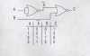
Logic levels (1=on, 0=off)
Temp Voltage Output(fan)
1 0 1
1 1 0
0 1 0
0 0 0

I have loads of NAND, NOR and AND gates available. Can the two unused comparators in the 339 be put to good use.
 
Change the inputs of voltage monitor comparator, and You can use AND gate. For lower current use simply a NAND-schmitt-trigger IC e.g. CD4093 instead of comparator. (or a CMOS comparator, but 4093 can do this, and only one 14pin package.)
 
voltage comparator CMOS

Thanks Sebi.
I thought my idea was foolproof, but......
can you give more info about using a 4093 as a dual comparator, and using its outputs to switch a power MOSFET ? Any circuits would be very useful. How does your idea handle my logic gate requirements? I know that CMOS use only microamps when not switching, so better than LM339. Thanks
 
Keep in mind that a NOR gate is also an inverted AND. I think this is the logic you are looking for:
 

Attachments

  • gates.jpg
    gates.jpg
    14.2 KB · Views: 702
CMOS gates

Thanks for the truth table. It's a great help.
Have you any ideas about using a 4093 NAND as a voltage comparator, like Sebi suggested, to save power and provide extra logic gates?
I've never seen a 4093 comparator circuit - they all use opamps of some kind.
 
The first gate work as supply voltage comparator.
FET must be a logic level triggered type.
 

Attachments

  • comp_839.gif
    comp_839.gif
    3.3 KB · Views: 687
CMOS gates

Thanks for the circuit Sebi. I'll make this up on breadboard. I found that the current of 12mA was produced by the 5V6 zener diode reference voltage - this needs at least 10mA to work, so was causing problems. I hope the 4093 will be much lower power.
Thanks for the CMOS idea. This deserves to be better known.
 
CMOS as comparator

Thanks for the revised circuit. The original one you sent didn't quite work as expected - the voltage comparator part permanently stopped the temp sensor part from working. If they were disconnected, the temp sensor worked fine on it own, without the voltage comparator. This new circuit looks an improvement on the first one. Have you got a theoretical value for the current flowing through the zener ? In my original op-amp comparator, this took 12mA (90% of the supply current to the op amp!)
I'll make this up on breadboard. I'm using a BUZ11 as the MOSFET. Is that OK? Regards
 
Yes, sorry, i've drawed it too quickly :oops:
The schmitt-trigger threshold depend from supply voltage, so need a zener diode. ZPD types happy with 0.5..1mA, i've tryed it. Go up the Z-voltage 6.8..7.5V, this better for BUZ11 gate.
Z=6.8V, pull-up resistor (poti+R) 200k switch off about 9.8V.
 
Status
Not open for further replies.

New Articles From Microcontroller Tips

Back
Top