Continue to Site

Welcome to our site!

Electro Tech is an online community (with over 170,000 members) who enjoy talking about and building electronic circuits, projects and gadgets. To participate you need to register. Registration is free. Click here to register now.

  • Welcome to our site! Electro Tech is an online community (with over 170,000 members) who enjoy talking about and building electronic circuits, projects and gadgets. To participate you need to register. Registration is free. Click here to register now.

help with break beam sensor

Status
Not open for further replies.

deuce01

New Member
Hey guys, Im new to electronics and circuits but im fairly good at residential wiring and building stuff. Im wanting to build a break beam sensor to turn on a light ( for a staging light for ATV drag racing). The sensors need to be able to be spread 6' to 8' apart. I have found several diagrams but am unable to understand them. Does some one have a diagram that is a little more user friendly to a novice builder. Also, i am currently have the staging lights built to where i can plug them in to an outlet and turn the lights on by a light switch, Is there any way to hook a sensor to this are will the lights have to be run off of 9v battery or something. Im sorry if this is the wrong place to post this or it is a dumb question. I have searched and searched and have not been able to find anything close to what i am wanting to build. Any help will be greatly appreciated.
 
how about using a laser diode (pointer) for each lane, w/ a sensor. do a search in these forums for .. dark/light sensor (use the laser diode) , laser alarm, walkway lights.
that should get you headed in the rite direction for starters.
 
The sensors need to be able to be spread 6' to 8' apart.
:confused: Does one 'sensor' consist of a light transmitter spaced 6' to 8' from a light detector?
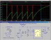
I have found several diagrams
Can you link to them, so that we can get some idea of your skill level?
 
How about just using garage door safety sensors?
 
Have you checked the 'Light/laser circuits' under the Circuits tab on this site? Might be something there to start from.
 
BeamBreak Detector based on Liftmaster 41A5034 Garage Door Opener Safety Beam Kit

I have a Liftmaster 41A5034 Garage Door Opener Safety Beam Kit that I bought to replace an intermittent sender on one of my garage doors several weeks ago, from here.

I hooked up the sender and receiver to a simple dc power supply tonight, and made some basic measurements. I was reliably able to get a range of >30ft. They operate on ~6Vdc, at low current. The receiver puts out a pulse train when illuminated as shown on the movie (not a simple dc level). I am designing a simple interface to pull-in a relay or drive a SSR when the beam is broken, and will post it soon.

To figure out how to wire this up, I had to get out a ladder, and find the Thevenin Equivalent of the power supply inside the Garage Door Opener. That is where the 6.3Vdc open circuit in series with a 51Ω resistor came from :D

ps- here it is the circuit. It will drive either a 5V relay, or a Solid-State-Relay. It requires a small DC power supply, could be a surplus DC Wall-Wart ,a 6V Lantern Battery, or 4 D-cells.

As long as the beam makes it from the Tx to the Rx, the Rx pulses its wires such that it pulls the voltage across it to near zero Volts. See the red trace V(wht-blk) in the simulation. If the beam is broken, the Rx stops pulsing. The 51Ω resistor R1 provides a load resistor across which the pulse appears.

To actuate a relay or SSR, I had to detect the cessation of the pulses. I'm using a 555 as a re-triggerable monostable; each pulse resets the timing circuit, see green trace V(rc). A few mS after the beam is broken, after the last pulse in the stream of pulses, the voltage at V(rc) rises to allow the output of the 555 blue trace V(out) to switch low, pulling-in the relay or turning on an SSR. If you use an SSR in place of the relay, you can leave out the snubber diode D2.

V3, the DC power supply is not particularly critical; anything from 5Vdc to 8Vdc will work. I used an old 5.5Vdc cell-phone wall-wart charger...
 

Attachments

  • BeamBreaka.jpg
    BeamBreaka.jpg
    138.7 KB · Views: 844
Last edited:
deuce01, you still out there?
 
Yea mike, Im still here. Sorry, dont get to check back here as much as i would like to. I really like your last post. It actually could understand it a little. Thanks for your help
 
After thinking over what i need, I think laser break beam may be better for my application due to it being a wireless device. Im not throwing out the garage door safety switch, just looking more into the Laser setup right now. So, does anyone have a simple wiring diagram that they could share with me? Thanks
 
See Post 10.
 
Last edited:
MikeMi,

I have looked at your Sept 12, 2012 post of a breakbean sensor switch circuit and it is exactly what I am look for!!

I want to mount a spare pair of safety beans higher up on the garage door at the bumper level. Then when the car is pulling into the garage (beam broken) a red stop light mounted on the front wall of the garage is off. Once the car is all the way into the garage (beam unbroken) a relay switch connected to your circuit will turn the stop light on. As additional info on my plan, I will splice into the AC wires of the garage door opener lights, which in turn will power a 6VDC wall wart into your breakbeam sensor circuit. This allows the circuit and stop light to automatically to go on/off when the garage door opener turns its light on and off.

So, I am brand new at electronics as I am just starting this hobby about 2 months ago. Reviewing your post and diagram, I have a few questions if you don't mind:
  • I see resistors R1, R3 and R4. Is there a R2 not shown or am I missing something?
  • Right below R3 there is a junction marked "rc". What does this mean?
  • What is the component to the right of D2? Trying to match up the symbol, is this an inducer? What does it do, where do I get one, and is there any value associated with this component?
  • Am I correct in that the output of the NE555 IC will be low (o volts) when the beam is unbroken, and go high (5 volts) when the beam is broken? Or do I have that reversed?
I thank you for any input you can give me. This will be my first real life project that is actually useful and be installed as a permanent gadget. I'm excited!!

Jim Smith
Dallas, TX
 
Welcome Jim,

MikeMi,... Reviewing your post and diagram, I have a few questions if you don't mind:
  • I see resistors R1, R3 and R4. Is there a R2 not shown or am I missing something?
  • Ignore that they are not consecutive... the Rs are just reference designators; nothing says they have to be consecutive, other than an pathologically ordered mind;)
  • Right below R3 there is a junction marked "rc". What does this mean?
  • I labeled that node in the schematic "rc" so that I could plot the voltage there (see V(rc) in the plot).
  • What is the component to the right of D2? Trying to match up the symbol, is this an inducer? What does it do, where do I get one, and is there any value associated with this component?
  • That is the coil of a 5Vdc relay, **broken link removed**
  • Am I correct in that the output of the NE555 IC will be low (o volts) when the beam is unbroken, and go high (5 volts) when the beam is broken? Or do I have that reversed?
  • Relay pulls-in (pin 3 goes low) when beam is broken and the pulses cease. See V(wht-blk) and V(out) in the plot.


ps: I cant get rid of the bullet dots in my reply...

pps: some wag will chime in to tell you to hang a tennis ball on a string... What is the fun in that?
 
Last edited:
Ah!! Things are beginning to clear. Mike, THANK YOU for your response as they were very helpful.

I'm going to order the diodes (which I don't have) and then breadboard it and see what happens. If all goes well, we'll see if I can then successfully build it all on a circuit board in a project box with nice plug in cables, etc. I'm sure by the third build (or so) it will work... But hey, this is what a hobby is all about.

And yeah, I've had the tennis ball on a string in the past. I have a laser now, but my short wife says she can't see it coming up on the dashboard, hence this little project. Maybe I can use a tennis ball as the project box?? That would be perfect!

Thanks again for the help. I'll update this once I get something working.
 
I use a foam stick (water pipe insulation) dropped to middle of windshield. She can't miss it.

Just raise the tennis ball and move forward to middle of glass in front of driver.
 
ps: I cant get rid of the bullet dots in my reply...

Select the bulleted stuff and the Bullets should be highlighted n the compose window. Click the Bullet icon in the compose window. Poof - Bullets should be gone. I quoted the post and did it, bullets vanished, but it looks like the quotes have to be added back.
 
Status
Not open for further replies.

Latest threads

New Articles From Microcontroller Tips

Back
Top