Continue to Site

Welcome to our site!

Electro Tech is an online community (with over 170,000 members) who enjoy talking about and building electronic circuits, projects and gadgets. To participate you need to register. Registration is free. Click here to register now.

  • Welcome to our site! Electro Tech is an online community (with over 170,000 members) who enjoy talking about and building electronic circuits, projects and gadgets. To participate you need to register. Registration is free. Click here to register now.

Help with boss hr2 Harmonist erratic voltage guitar pedal on an ic

Status
Not open for further replies.
Hello, in advance I thank people who can help or provide any comments that can help me.


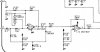
The question is this, I have a boss hr2 Harmonist guitar pedal. the pedal turns on, but it sounds like a very unpleasant and inaudible oscillation, I have checked the voltages as the diagram indicates and everything is correct except for the voltages in an ic (which by the way I cannot find to replace in case it is damaged this one) I attached the diagram and the voltages on the pins that I find with erratic voltage.

The problem is in IC8 and IC9 the pins of the IC8 with erratic voltage are pin 10, 13 and 15 presents an erratic reading that varies from 2.4 to 4 vol. but quickly, I also notice that the ic5 gets quite hot but I measured it and it is in good condition in the same way the ic9 on pins 13 and 15 its voltage is erratic

Any idea that I could be giving these problems? And if anyone thinks it is possible that the ic8 has to be replaced, where could he get that ic or some replacement?
 

Attachments

  • HR-2.pdf
    941.8 KB · Views: 276
I'd check or just replace the electrolytic capacitors in the power supply section to start with - C1, C4 & C17.

The 78L05 is a voltage regulator and the voltages on its pins should be absolutely constant.

Are you using a battery or external power unit? Using a 7805 series regulator is not good design practice in a device intended for operation on a 9V battery as such a battery is not formally flat until it reaches 6V - and a 7805/78L05 is supposed to have at least 7V input.

If the supply voltage to the input of the 78L05 is ever less than 7V, there are no guarantees that anything else can work properly.
If the output voltage is varying even with an external 9V supply, it could be a faulty 78L05 or it could be one of the other devices drawing excess current.


The varying voltages on IC8 & IC9 pins are nothing to be concerned about, they are address signals to the RAM, which are likely all cycling at different rates; those are the only ones slow enough for the meter to partially detect the changes.

IC8 is a custom-made / custom programmed device made by or for Boss for that specific pedal.
 
First of all thank you for your help, I commented that I had previously reviewed those capacitors and they are in good condition, but in the same way I will change them and also change the voltage regulator, the truth I can not find the error, but I will follow your advice and change the capacitors and I will let you know if there is any change.
 
am not an expert but i want to fix it, i have a question, the capacitor are C1=100uF/16v C4=100uF/6.3v and C17= 100uF/6.3v ?
 
apply current and watch what gets hot. Hand should be enough. Alcohol is handy. If chip gets hot make sure its on right voltage. Not exceed 3,3/5/12Volts according to right chip voltage. Not reversed polarity. If you dont have powersupply try to use bateries instead. Start with low voltages and rise until hot appears.
 
First of all thank you for your help, I commented that I had previously reviewed those capacitors and they are in good condition, but in the same way I will change them and also change the voltage regulator, the truth I can not find the error, but I will follow your advice and change the capacitors and I will let you know if there is any change.
There is no need to change cap. If they are not shorted or blowed. Measurre capacitence or conductance.
 
capacitor are C1=100uF/16v C4=100uF/6.3v and C17= 100uF/6.3v ?

Yes, the three that provide the main power decoupling.

Re. the other answer, they cannot be properly tested in circuit & if they are going to be removed, it's best to just fit new know-good ones.

What power supply are you using for testing the pedal?
 
Yes, the three that provide the main power decoupling.

Re. the other answer, they cannot be properly tested in circuit & if they are going to be removed, it's best to just fit new know-good ones.

What power supply are you using for testing the pedal?
Thats right. He need to desolder them before he can test them.
 
Thats right. He need to desolder them before he can test them.

Well the only way to test them is by measuring their ESR, which you can usually do in-circuit using an ESR meter, or by removing them and using a frequency generator and oscilloscope - there's no point measuring their capacitance, as that VERY often is fine even when the capacitor is totally shot.

However, in this case as it's not a switch-mode power supply, then the chances of the capacitors been at fault are relatively slim anyway.
 
The voltage at the output of the 78L05 is reportedly unstable.

IF the input supply is adequate (still not confirmed), the reg is either oscillating due to the caps drying up, or it's faulty - or the main CPU is likely dead, in which case the pedal is a write-off.

It's a admittedly a long shot, but having known good caps (and replacing the reg as the OP says he is going to do) eliminates the obvious cheaply-fixed causes without too much time or money expended.
 
Thanks for your answers, let us clarify some points.
Power supply: I use a laboratory power supply. 0to32v 2amp
capacitor: I took them out and checked them with my multimeter
Today I checked some voltages and described them below:

78l05: input: 9.05v output: 5.60vol
and this i mesure just to check the voltage in all ic

M5218AF (IC100,IC1,IC2)
IC100 ---- power + leg8: 5.02v output leg1: 2.766v
IC02 ---- power + leg8: 8.28v output leg1: 4.195v
IC01 ---- power + leg8: 8.28v output leg1: 4.196v


IC10 Leg17 Vcc=5,058v


NJM2100
IC-LEG-----------------------IC3 ------------- IC4
1.A output-------------------4.999v-----------3,366v
2.A -input-------------------4,995v------------3,364v
3.A +input-------------------0,017v------------3,376
4. V ---------------------------0------------------0
5.B +input--------------------5,058------------5,058
6.B -input--------------------4,999------------3.368
7. output----------------------4,989-----------3,366
8. V+----------------------------0,017------------3,379

in the picture i attach in all this area the vol its 2.65v or less i really dont remember but i can check


if you guys need extra information, pls ask and i send it, i really want to fix this pedal

forget to mention, that this pedal bought it damaged, but it was a 2-pedal package, the first one is already repaired, but when i was checking the first pedal and also this one, I found inside the PCB that they were damaged by being exposed to some liquid that at dry sticky, something like beer or soda
 

Attachments

  • 123123.jpg
    123123.jpg
    77.1 KB · Views: 223
Last edited:
i dont have a ESR tester but i guess they are ok, the voltage thru this its correct

this ist the multimeter the i use: **broken link removed**
 
Sorry Output for the 78L05 isn’t 5,60v it’s 5,060v it’s still not good?

OK, that is fine. If that is totally stable, or no more that a few tens of millivolts noise, then it does appear one of the other ICs may be at fault.
 
I noticed today after measuring the voltage of the 78L05 again, by accident I touched one of the diodes: D7, when I touch it it makes an even louder static noise, I touch it with my finger and then with a tool and it makes the same noise , but only touch it in the capsule not in the legs
 
Status
Not open for further replies.

Latest threads

New Articles From Microcontroller Tips

Back
Top