Will tieing IN11 And IN21 to earth And IN12 and IN22 to Vcc drive the Stepper Motor or am I missing something.
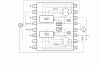
BA6845FS Datasheet pdf - Magnetic Disk LSIs > FDD stepping motor driver - ROHM
BA6845FS Datasheet pdf - Magnetic Disk LSIs > FDD stepping motor driver - ROHM